Cloud Application Architecture Guide
Choose an architecture style
The first decision you need to make when designing a cloud application is the architecture. Choose the best architecture for the application you are building based on its complexity, type of domain, if it's an IaaS or PaaS application, and what the application will do. Also consider the skills of the developer and DevOps teams, and if the application has an existing architecture.
An architecture style places constraints on the design, which guide the "shape" of an architecture style by restricting the choices. These constraints provide both benefits and challenges for the design. Use the information in this section to understand what the trade-offs are when adopting any of these styles.
This section describes ten design principles to keep in mind as you build. Following these principles will help you build an application that is more scalable, resilient, and manageable.
We have identified a set of architecture styles that are commonly found in cloud applications. The article for each style includes:
- A description and logical diagram of the style.
- Recommendations for when to choose this style.
- Benefits, challenges, and best practices.
- A recommended deployment using relevant Azure services.
A quick tour of the styles
This section gives a quick tour of the architecture styles that we've identified, along with some highlevel considerations for their use. Read more details in the linked topics.
N-tier
N-tier is a traditional architecture for enterprise applications. Dependencies are managed by dividing the application into layers that perform logical functions, such as presentation, business logic, and data access. A layer can only call into layers that sit below it. However, this horizontal layering can be a liability. It can be hard to introduce changes in one part of the application without touching the rest of the application. That makes frequent updates a challenge, limiting how quickly new features can be added.
N-tier is a natural fit for migrating existing applications that already use a layered architecture. For that reason, N-tier is most often seen in infrastructure as a service (IaaS) solutions, or applications that use a mix of IaaS and managed services.

Web-Queue-Worker
For a purely PaaS solution, consider a Web-Queue-Worker architecture. In this style, the application has a web front end that handles HTTP requests and a back-end worker that performs CPU-intensive tasks or long-running operations. The front end communicates to the worker through an asynchronous message queue.
Web-queue-worker is suitable for relatively simple domains with some resource-intensive tasks. Like N-tier, the architecture is easy to understand. The use of managed services simplifies deployment and operations. But with complex domains, it can be hard to manage dependencies. The front end and the worker can easily become large, monolithic components that are hard to maintain and update. As with N-tier, this can reduce the frequency of updates and limit innovation.

Microservices
If your application has a more complex domain, consider moving to a Microservices architecture. A microservices application is composed of many small, independent services. Each service implements a single business capability. Services are loosely coupled, communicating through API contracts.
Each service can be built by a small, focused development team. Individual services can be deployed without a lot of coordination between teams, which encourages frequent updates. A microservice architecture is more complex to build and manage than either N-tier or web-queue-worker. It requires a mature development and DevOps culture. But done right, this style can lead to higher release velocity, faster innovation, and a more resilient architecture.

CQRS
The CQRS (Command and Query Responsibility Segregation) style separates read and write operations into separate models. This isolates the parts of the system that update data from the parts that read the data. Moreover, reads can be executed against a materialized view that is physically separate from the write database. That lets you scale the read and write workloads independently, and optimize the materialized view for queries.
CQRS makes the most sense when it's applied to a subsystem of a larger architecture. Generally, you shouldn't impose it across the entire application, as that will just create unneeded complexity. Consider it for collaborative domains where many users access the same data.

Event-Driven Architecture
Event-Driven Architectures use a publish-subscribe (pub-sub) model, where producers publish events, and consumers subscribe to them. The producers are independent from the consumers, and consumers are independent from each other.
Consider an event-driven architecture for applications that ingest and process a large volume of data with very low latency, such as IoT solutions. This style is also useful when different subsystems must perform different types of processing on the same event data.

Big Data, Big Compute
Big Data and Big Compute are specialized architecture styles for workloads that fit certain specific profiles. Big data divides a very large dataset into chunks, performing paralleling processing across the entire set, for analysis and reporting. Big compute, also called high-performance computing (HPC), makes parallel computations across a large number (thousands) of cores. Domains include simulations, modeling, and 3-D rendering.
Architecture styles as constraints
An architecture style places constraints on the design, including the set of elements that can appear and the allowed relationships between those elements. Constraints guide the "shape" of an architecture by restricting the universe of choices. When an architecture conforms to the constraints of a particular style, certain desirable properties emerge.
For example, the constraints in microservices include:
- A service represents a single responsibility.
- Every service is independent of the others.
- Data is private to the service that owns it. Services do not share data.
By adhering to these constraints, what emerges is a system where services can be deployed independently, faults are isolated, frequent updates are possible, and it's easy to introduce new technologies into the application.
Before choosing an architecture style, make sure that you understand the underlying principles
and constraints of that style. Otherwise, you can end up with a design that conforms to the style at a superficial level, but does not achieve the full potential of that style. It's also important to be pragmatic. Sometimes it's better to relax a constraint, rather than insist on architectural purity.
The following table summarizes how each style manages dependencies, and the types of domain that are best suited for each.
Architecture style | Dependency management | Domain type |
N-tier | Horizontal tiers divided by subnet. | Traditional business domain. Frequency of updates is low. |
Web-Queue-Worker | Front and backend jobs, decoupled by async messaging. | Relatively simple domain with some resource intensive tasks. |
Microservices | Vertically (functionally) decomposed services that call each other through APIs. | Complicated domain. Frequent updates. |
CQRS | Read/write segregation. Schema and scale are optimized separately. | Collaborative domain where lots of users access the same data. |
Event-driven architecture | Producer/consumer. Independent view per sub-system. | IoT and real-time systems. |
Big data | Divide a huge dataset into small chunks. Parallel processing on local datasets. | Batch and real-time data analysis. Predictive analysis using ML. |
Big compute | Data allocation to thousands of cores. | Compute intensive domains such as simulation. |
Consider challenges and benefits
Constraints also create challenges, so it's important to understand the trade-offs when adopting any of these styles. Do the benefits of the architecture style outweigh the challenges, for this subdomain and bounded context?
Here are some of the types of challenges to consider when selecting an architecture style:
- Complexity. Is the complexity of the architecture justified for your domain? Conversely, is the style too simplistic for your domain? In that case, you risk ending up with a "ball of mud", becuase the architecture does not help you to manage dependencies cleanly.
- Asynchronous messaging and eventual consistency. Asynchronous messaging can be used to decouple services, and increase reliability (because messages can be retried) and scalability. However, this also creates challenges such as always-once semantics and eventual consistency.
- Inter-service communication. As you decompose an application into separate services, there is a risk that communication between services will cause unacceptable latency or create network congestion (for example, in a microservices architecture).
- Manageability. How hard is it to manage the application, monitor, deploy updates, and so on?
N-tier architecture style
An N-tier architecture divides an application into logical layers and physical tiers.
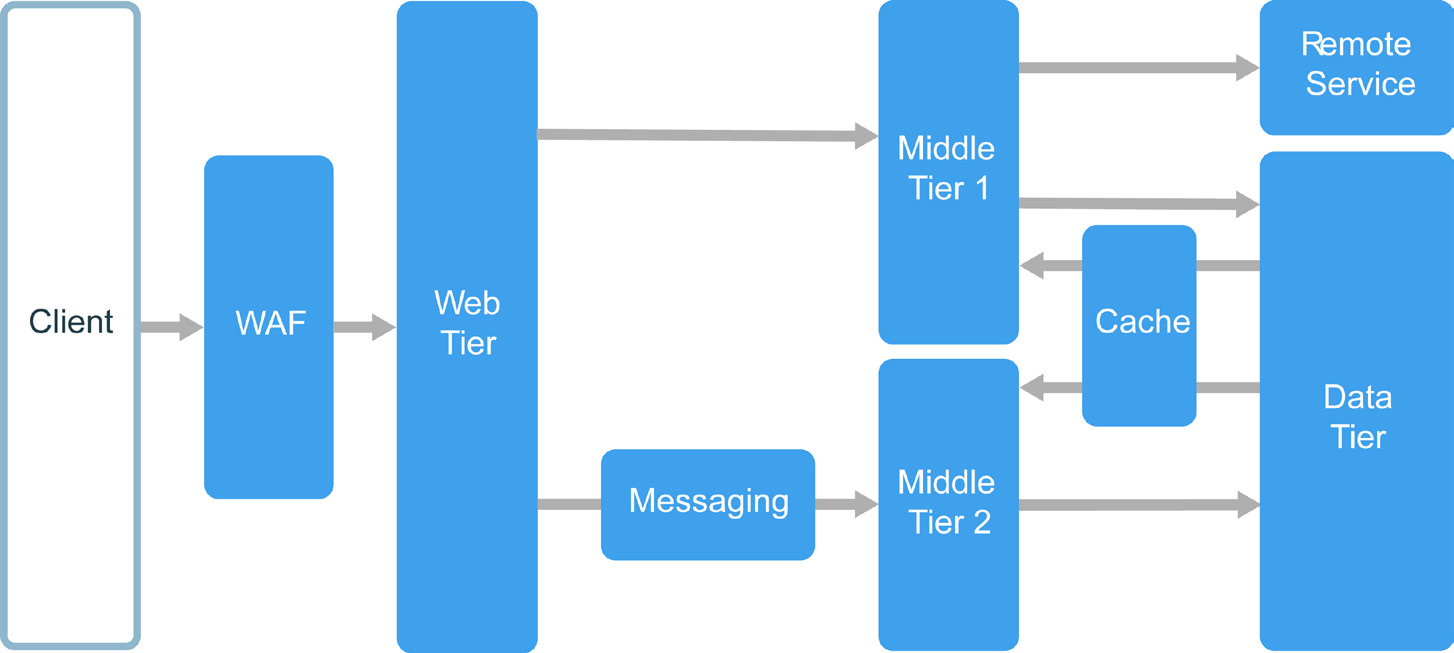
Layers are a way to separate responsibilities and manage dependencies. Each layer has a specific responsibility. A higher layer can use services in a lower layer, but not the other way around.
Tiers are physically separated, running on separate machines. A tier can call to another tier directly, or use asynchronous messaging (message queue). Although each layer might be hosted in its own tier, that's not required. Several layers might be hosted on the same tier. Physically separating the tiers improves scalability and resiliency, but also adds latency from the additional network communication. A traditional three-tier application has a presentation tier, a middle tier, and a database tier. The middle tier is optional. More complex applications can have more than three tiers. The diagram above shows an application with two middle tiers, encapsulating different areas of functionality.
An N-tier application can have a closed layer architecture or an open layer architecture:
- In a closed layer architecture, a layer can only call the next layer immediately down
- In an open layer architecture, a layer can call any of the layers below it.
A closed layer architecture limits the dependencies between layers. However, it might create unnecessary network traffic, if one layer simply passes requests along to the next layer.
When to use this architecture
N-tier architectures are typically implemented as infrastructure-as-a-service (IaaS) applications, with each tier running on a separate set of VMs. However, an N-tier application doesn't need to be pure IaaS. Often, it's advantageous to use managed services for some parts of the architecture, particularly caching, messaging, and data storage.
Consider an N-tier architecture for:
- Simple web applications.
- Migrating an on-premises application to Azure with minimal refactoring.
- Unified development of on-premises and cloud applications.
N-tier architectures are very common in traditional on-premises applications, so it's a natural fit for migrating existing workloads to Azure.
Benefits
- Portability between cloud and on-premises, and between cloud platforms.
- Less learning curve for most developers.
- Natural evolution from the traditional application model.
- Open to heterogeneous environment (Windows/Linux)
Challenges
- It's easy to end up with a middle tier that just does CRUD operations on the database, adding extra latency without doing any useful work.
- Monolithic design prevents independent deployment of features.
- Managing an IaaS application is more work than an application that uses only managed services.
- It can be difficult to manage network security in a large system.
Best practices
- Use autoscaling to handle changes in load. See Autoscaling best practices.
- Use asynchronous messaging to decouple tiers.
- Cache semi-static data. See Caching best practices.
- Configure database tier for high availability, using a solution such as SQL Server Always On Availability Groups.
- Place a web application firewall (WAF) between the front end and the Internet.
- Place each tier in its own subnet, and use subnets as a security boundary.
- Restrict access to the data tier, by allowing requests only from the middle tier(s).
N-tier architecture on virtual machines
This section describes a recommended N-tier architecture running on VMs.

This section describes a recommended N-tier architecture running on VMs. Each tier consists of two or more VMs, placed in an availability set or VM scale set. Multiple VMs provide resiliency in case one VM fails. Load balancers are used to distribute requests across the VMs in a tier. A tier can be scaled horizontally by adding more VMs to the pool.
Each tier is also placed inside its own subnet, meaning their internal IP addresses fall within the same address range. That makes it easy to apply network security group (NSG) rules and route tables to individual tiers.
The web and business tiers are stateless. Any VM can handle any request for that tier. The data tier should consist of a replicated database. For Windows, we recommend SQL Server, using Always On Availability Groups for high availability. For Linux, choose a database that supports replication, such as Apache Cassandra.
Network Security Groups (NSGs) restrict access to each tier. For example, the database tier only allows access from the business tier.
For more details and a deployable Resource Manager template, see the following reference architectures:
Run Windows VMs for an N-tier application
Run Linux VMs for an N-tier application
Additional considerations
- N-tier architectures are not restricted to three tiers. For more complex applications, it is common to have more tiers. In that case, consider using layer-7 routing to route requests to a particular tier.
- Tiers are the boundary of scalability, reliability, and security. Consider having separate tiers for services with different requirements in those areas.
- Use VM Scale Sets for autoscaling.
- Look for places in the architecture where you can use a managed service without significant refactoring. In particular, look at caching, messaging, storage, and databases.
- For higher security, place a network DMZ in front of the application. The DMZ includes network virtual appliances (NVAs) that implement security functionality such as firewalls and packet inspection. For more information, see Network DMZ reference architecture.
- For high availability, place two or more NVAs in an availability set, with an external load balancer to distribute Internet requests across the instances. For more information, see Deploy highly available network virtual appliances.
- Do not allow direct RDP or SSH access to VMs that are running application code. Instead, operators should log into a jumpbox, also called a bastion host. This is a VM on the network that administrators use to connect to the other VMs. The jumpbox has an NSG that allows RDP or SSH only from approved public IP addresses.
- You can extend the Azure virtual network to your on-premises network using a site-to-site virtual private network (VPN) or Azure ExpressRoute. For more information, see Hybrid network reference architecture.
- If your organization uses Active Directory to manage identity, you may want to extend your Active Directory environment to the Azure VNet. For more information, see Identity management reference architecture.
- If you need higher availability than the Azure SLA for VMs provides, replicate the application across two regions and use Azure Traffic Manager for failover. For more information, see Run Windows VMs in multiple regions or Run Linux VMs in multiple regions.
Web-QueueWorker architecture style
The core components of this architecture are a web front end that serves client requests, and a worker that performs resource-intensive tasks, longrunning workflows, or batch jobs. The web front end communicates with the worker through a message queue.

Other components that are commonly incorporated into this architecture include:
- One or more databases.
- A cache to store values from the database for quick reads.
- CDN to serve static content.
The web and worker are both stateless. Session state can be stored in a distributed cache. Any long- running work is done asynchronously by the worker. The worker can be triggered by messages on the queue, or run on a schedule for batch processing. The worker is an optional component. If there are no long-running operations, the worker can be omitted.
The front end might consist of a web API. On the client side, the web API can be consumed by a single-page application that makes AJAX calls, or by a native client application.
When to use this architecture
The Web-Queue-Worker architecture is typically implemented using managed compute services, either Azure App Service or Azure Cloud Services.
Consider this architecture style for:
- Applications with a relatively simple domain.
- Applications with some long-running workflows or batch operations.
- When you want to use managed services, rather than infrastructure as a service (IaaS).
Benefits
- Relatively simple architecture that is easy to understand.
- Easy to deploy and manage.
- Clear separation of concerns.
- The front end is decoupled from the worker using asynchronous messaging.
- The front end and the worker can be scaled independently.
Challenges
- Without careful design, the front end and the worker can become large, monolithic components that are difficult to maintain and update.
- There may be hidden dependencies, if the front end and worker share data schemas or code modules.
Best practices
- Use polyglot persistence when appropriate. See Use the best data store for the job.
- For best practices articles that provide specific guidance on auto-scaling, caching, data partitioning, API design, and more, go to https://docs.microsoft.com/en-us/azure/architecture/ best-practices/index.
Web-Queue-Worker on Azure App Service
This section describes a recommended Web-Queue-Worker architecture that uses Azure App Service.

The front end is implemented as an Azure App Service web app, and the worker is implemented as a WebJob. The web app and the WebJob are both associated with an App Service plan that provides the VM instances.
You can use either Azure Service Bus or Azure Storage queues for the message queue. (The diagram shows an Azure Storage queue.)
Azure Redis Cache stores session state and other data that needs low latency access.
Azure CDN is used to cache static content such as images, CSS, or HTML.
For storage, choose the storage technologies that best fit the needs of the application. You might use multiple storage technologies (polyglot persistence). To illustrate this idea, the diagram shows Azure SQL Database and Azure Cosmos DB.
For more details, see Managed web application reference architecture.
Additional considerations
- Not every transaction has to go through the queue and worker to storage. The web front end can perform simple read/write operations directly. Workers are designed for resource-intensive tasks or long-running workflows. In some cases, you might not need a worker at all.
- Use the built-in autoscale feature of App Service to scale out the number of VM instances. If the load on the application follows predictable patterns, use schedule-based autoscale. If the load is unpredictable, use metrics-based autoscaling rules.
- Consider putting the web app and the WebJob into separate App Service plans. That way, they are hosted on separate VM instances and can be scaled independently.
- Use separate App Service plansa for production and testing. Otherwise, if you use the same plan for production and testing, it means your tests are running on your production VMs. • Use deployment slots to manage deployments. This lets you to deploy an updated version to a staging slot, then swap over to the new version. It also lets you swap back to the previous version, if there was a problem with the update.
Microservices architecture style
A microservices architecture consists of a collection of small, autonomous services. Each service is self-contained and should implement a single business capability.

In some ways, microservices are the natural evolution of service oriented architectures (SOA), but there are differences between microservices and SOA. Here are some defining characteristics of a microservice:
- In a microservices architecture, services are small, independent, and loosely coupled.
- Each service is a separate codebase, which can be managed by a small development team.
- Services can be deployed independently. A team can update an existing service without rebuilding and redeploying the entire application.
- Services are responsible for persisting their own data or external state. This differs from the traditional model, where a separate data layer handles data persistence.
- Services communicate with each other by using well-defined APIs. Internal implementation details of each service are hidden from other services.
- Services don't need to share the same technology stack, libraries, or frameworks.
Besides for the services themselves, some other components appear in a typical microservices architecture:
- Management. The management component is responsible for placing services on nodes, identifying failures, rebalancing services across nodes, and so forth.
- Service Discovery. Maintains a list of services and which nodes they are located on. Enables service lookup to find the endpoint for a service.
- API Gateway. The API gateway is the entry point for clients. Clients don't call services directly. Instead, they call the API gateway, which forwards the call to the appropriate services on the back end. The API gateway might aggregate the responses from several services and return the aggregated response.
The advantages of using an API gateway include:
- It decouples clients from services. Services can be versioned or refactored without needing to update all of the clients.
- Services can use messaging protocols that are not web friendly, such as AMQP.
- The API Gateway can perform other cross-cutting functions such as authentication, logging, SSL termination, and load balancing.
When to use this architecture
Consider this architecture style for:
- Large applications that require a high release velocity.
- Complex applications that need to be highly scalable.
- Applications with rich domains or many subdomains.
- An organization that consists of small development teams.
Benefits
- Independent deployments. You can update a service without redeploying the entire application, and roll back or roll forward an update if something goes wrong. Bug fixes and feature releases are more manageable and less risky.
- Independent development. A single development team can build, test, and deploy a service. The result is continuous innovation and a faster release cadence.
- Small, focused teams. Teams can focus on one service. The smaller scope of each service makes the code base easier to understand, and it's easier for new team members to ramp up.
- Fault isolation. If a service goes down, it won't take out the entire application. However, that doesn't mean you get resiliency for free. You still need to follow resiliency best practices and design patterns. See Designing resilient applications for Azure.
- Mixed technology stacks. Teams can pick the technology that best fits their service.
- Granular scaling. Services can be scaled independently. At the same time, the higher density of services per VM means that VM resources are fully utilized. Using placement constraints, a services can be matched to a VM profile (high CPU, high memory, and so on).
Challenges
- Complexity. A microservices application has more moving parts than the equivalent monolithic application. Each service is simpler, but the entire system as a whole is more complex.
- Development and test. Developing against service dependencies requires a different approach. Existing tools are not necessarily designed to work with service dependencies. Refactoring across service boundaries can be difficult. It is also challenging to test service dependencies, especially when the application is evolving quickly.
- Lack of governance. The decentralized approach to building microservices has advantages, but it can also lead to problems. You may end up with so many different languages and frameworks that the application becomes hard to maintain. It may be useful to put some project-wide standards in place, without overly restricting teams' flexibility. This especially applies to crosscutting functionality such as logging.
- Network congestion and latency. The use of many small, granular services can result in more interservice communication. Also, if the chain of service dependencies gets too long (service A calls B, which calls C...), the additional latency can become a problem. You will need to design APIs carefully. Avoid overly chatty APIs, think about serialization formats, and look for places to use asynchronous communication patterns.
- Data integrity. With each microservice responsible for its own data persistence. As a result, data consistency can be a challenge. Embrace eventual consistency where possible.
- Management. To be successful with microservices requires a mature DevOps culture. Correlated logging across services can be challenging. Typically, logging must correlate multiple service calls for a single user operation.
- Versioning. Updates to a service must not break services that depend on it. Multiple services could be updated at any given time, so without careful design, you might have problems with backward or forward compatibility.
- Skillset. Microservices are highly distributed systems. Carefully evaluate whether the team has the skills and experience to be successful.
Best practices
- Model services around the business domain. • Decentralize everything. Individual teams are responsible for designing and building services. Avoid sharing code or data schemas.
- Data storage should be private to the service that owns the data. Use the best storage for each service and data type.
- Services communicate through well-designed APIs. Avoid leaking implementation details. APIs should model the domain, not the internal implementation of the service.
- Avoid coupling between services. Causes of coupling include shared database schemas and rigid communication protocols.
- Offload cross-cutting concerns, such as authentication and SSL termination, to the gateway.
- Keep domain knowledge out of the gateway. The gateway should handle and route client requests without any knowledge of the business rules or domain logic. Otherwise, the gateway becomes a dependency and can cause coupling between services.
- Services should have loose coupling and high functional cohesion. Functions that are likely to change together should be packaged and deployed together. If they reside in separate services, those services end up being tightly coupled, because a change in one service will require updating the other service. Overly chatty communication between two services may be a symptom of tight coupling and low cohesion.
- Isolate failures. Use resiliency strategies to prevent failures within a service from cascading. See designing resilient applications.
For a list and summary of the resiliency patterns available in Azure, go to https://docs.microsoft.com/ en-us/azure/architecture/patterns/category/resiliency.
Microservices using Azure Container Service
You can use Azure Container Service to configure and provision a Docker cluster. Azure Container Services supports several popular container orchestrators, including Kubernetes, DC/OS, and Docker Swarm.

Public nodes. These nodes are reachable through a public-facing load balancer. The API gateway is hosted on these nodes.
Backend nodes. These nodes run services that clients reach via the API gateway. These nodes don't receive Internet traffic directly. The backend nodes might include more than one pool of VMs, each with a different hardware profile. For example, you could create separate pools for general compute workloads, high CPU workloads, and high memory workloads.
Management VMs. These VMs run the master nodes for the container orchestrator.
Networking. The public nodes, backend nodes, and management VMs are placed in separate subnets within the same virtual network (VNet).
Load balancers. An externally facing load balancer sits in front of the public nodes. It distributes internet requests to the public nodes. Another load balancer is placed in front of the management VMs, to allow secure shell (ssh) traffic to the management VMs, using NAT rules.
For reliability and scalability, each service is replicated across multiple VMs. However, because services are also relatively lightweight (compared with a monolithic application), multiple services are usually packed into a single VM. Higher density allows better resource utilization. If a particular service doesn't use a lot of resources, you don't need to dedicate an entire VM to running that service.
The following diagram shows three nodes running four different services (indicated by different shapes). Notice that each service has at least two instances.

Microservices using Azure Service Fabric
The following diagram shows a microservices architecture using Azure Service Fabric.

The Service Fabric Cluster is deployed to one or more VM scale sets. You might have more than one VM scale set in the cluster, in order to have a mix of VM types. An API Gateway is placed in front of the Service Fabric cluster, with an external load balancer to receive client requests.
The Service Fabric runtime performs cluster management, including service placement, node failover, and health monitoring. The runtime is deployed on the cluster nodes themselves. There isn't a separate set of cluster management VMs.
Services communicate with each other using the reverse proxy that is built into Service Fabric. Service Fabric provides a discovery service that can resolve the endpoint for a named service.
CQRS architecture style
Command and Query Responsibility Segregation (CQRS) is an architecture style that separates read operations from write operations.

In traditional architectures, the same data model is used to query and update a database. That's simple and works well for basic CRUD operations. In more complex applications, however, this approach can become unwieldy. For example, on the read side, the application may perform many different queries, returning data transfer objects (DTOs) with different shapes. Object mapping can become complicated. On the write side, the model may implement complex validation and business logic. As a result, you can end up with an overly complex model that does too much.
Another potential problem is that read and write workloads are often asymmetrical, with very different performance and scale requirements.
CQRS addresses these problems by separating reads and writes into separate models, using commands to update data, and queries to read data.
- Commands should be task based, rather than data centric. ("Book hotel room," not "set ReservationStatus to Reserved.") Commands may be placed on a queue for asynchronous processing, rather than being processed synchronously.
- Queries never modify the database. A query returns a DTO that does not encapsulate any domain knowledge.
For greater isolation, you can physically separate the read data from the write data. In that case, the read database can use its own data schema that is optimized for queries. For example, it can store a materialized view of the data, in order to avoid complex joins or complex O/RM mappings. It might even use a different type of data store. For example, the write database might be relational, while the read database is a document database.
If separate read and write databases are used, they must be kept in sync. Typically this is accomplished by having the write model publish an event whenever it updates the database. Updating the database and publishing the event must occur in a single transaction.
Some implementations of CQRS use the Event Sourcing pattern. With this pattern, application state is stored as a sequence of events. Each event represents a set of changes to the data. The current state is constructed by replaying the events. In a CQRS context, one benefit of Event Sourcing is that the same events can be used to notify other components — in particular, to notify the read model. The read model uses the events to create a snapshot of the current state, which is more efficient for queries. However, Event Sourcing adds complexity to the design.

When to use this architecture
Consider CQRS for collaborative domains where many users access the same data, especially when the read and write workloads are asymmetrical.
CQRS is not a top-level architecture that applies to an entire system. Apply CQRS only to those subsystems where there is clear value in separating reads and writes. Otherwise, you are creating additional complexity for no benefit.
Benefits
- Independently scaling. CQRS allows the read and write workloads to scale independently, and may result in fewer lock contentions.
- Optimized data schemas. The read side can use a schema that is optimized for queries, while the write side uses a schema that is optimized for updates.
- Security. It's easier to ensure that only the right domain entities are performing writes on the data.
- Separation of concerns. Segregating the read and write sides can result in models that are more maintainable and flexible. Most of the complex business logic goes into the write model. The read model can be relatively simple.
- Simpler queries. By storing a materialized view in the read database, the application can avoid complex joins when querying.
Challenges
- Complexity. The basic idea of CQRS is simple. But it can lead to a more complex application design, especially if they include the Event Sourcing pattern.
- Messaging. Although CQRS does not require messaging, it's common to use messaging to process commands and publish update events. In that case, the application must handle message failures or duplicate messages.
- Eventual consistency. If you separate the read and write databases, the read data may be stale.
Best practices
- For more information about implementing CQRS, go to https://docs.microsoft.com/en-us/azure/ architecture/patterns/cqrs.
- For information about using the Event Sourcing pattern to avoid update conflicts, go to https:// docs.microsoft.com/en-us/azure/architecture/patterns/event-sourcing.
- For information about using the Materialized View pattern for the read model, to optimize the schema for queries, go to https://docs.microsoft.com/en-us/azure/architecture/patterns/ materialized-view.
CQRS in microservices
CQRS can be especially useful in a microservices architecture. One of the principles of microservices is that a service cannot directly access another service's data store.

In the following diagram, Service A writes to a data store, and Service B keeps a materialized view of the data. Service A publishes an event whenever it writes to the data store. Service B subscribes to the event.

Event-driven architecture style
An event-driven architecture consists of event producers that generate a stream of events, and event consumers that listen for the events.

Events are delivered in near real time, so consumers can respond immediately to events as they occur. Producers are decoupled from consumers — a producer doesn't know which consumers are listening. Consumers are also decoupled from each other, and every consumer sees all of the events. This differs from a Competing Consumers pattern, where consumers pull messages from a queue and a message is processed just once (assuming no errors). In some systems, such as IoT, events must be ingested at very high volumes.
An event driven architecture can use a pub/sub model or an event stream model.
- Pub/sub: The messaging infrastructure keeps track of subscriptions. When an event is published, it sends the event to each subscriber. After an event is received, it cannot be replayed, and new subscribers do not see the event.
- Event streaming: Events are written to a log. Events are strictly ordered (within a partition) and durable. Clients don't subscribe to the stream, instead a client can read from any part of the stream. The client is responsible for advancing its position in the stream. That means a client can join at any time, and can replay events.
On the consumer side, there are some common variations:
- Simple event processing. An event immediately triggers an action in the consumer. For example, you could use Azure Functions with a Service Bus trigger, so that a function executes whenever a message is published to a Service Bus topic.
- Complex event processing. A consumer processes a series of events, looking for patterns in the event data, using a technology such as Azure Stream Analytics or Apache Storm. For example, you could aggregate readings from an embedded device over a time window, and generate a notification if the moving average crosses a certain threshold.
- Event stream processing. Use a data streaming platform, such as Azure IoT Hub or Apache Kafka, as a pipeline to ingest events and feed them to stream processors. The stream processors act to process or transform the stream. There may be multiple stream processors for different subsystems of the application. This approach is a good fit for IoT workloads.
The source of the events may be external to the system, such as physical devices in an IoT solution. In that case, the system must be able to ingest the data at the volume and throughput that is required by the data source.
In the logical diagram above, each type of consumer is shown as a single box. In practice, it's common to have multiple instances of a consumer, to avoid having the consumer become a single point of failure in system. Multiple instances might also be necessary to handle the volume and frequency of events. Also, a single consumer might process events on multiple threads. This can create challenges if events must be processed in order, or require exactly-once semantics. See Minimize Coordination.
When to use this architecture
- Multiple subsystems must process the same events.
- Real-time processing with minimum time lag.
- Complex event processing, such as pattern matching or aggregation over time windows.
- High volume and high velocity of data, such as IoT.
Benefits
- Producers and consumers are decoupled.
- No point-to point-integrations. It's easy to add new consumers to the system.
- Consumers can respond to events immediately as they arrive.
- Highly scalable and distributed.
- Subsystems have independent views of the event stream.
Challenges
- Guaranteed delivery. In some systems, especially in IoT scenarios, it's crucial to guarantee that events are delivered.
- Processing events in order or exactly once. Each consumer type typically runs in multiple instances, for resiliency and scalability. This can create a challenge if the events must be processed in order (within a consumer type), or if the processing logic is not idempotent.
IoT architecture
Event-driven architectures are central to IoT solutions. The following diagram shows a possible logical architecture for IoT. The diagram emphasizes the event-streaming components of the architecture.

The cloud gateway ingests device events at the cloud boundary, using a reliable, low latency messaging system.
Devices might send events directly to the cloud gateway, or through a field gateway. A field gateway is a specialized device or software, usually colocated with the devices, that receives events and forwards them to the cloud gateway. The field gateway might also preprocess the raw device events, performing functions such as filtering, aggregation, or protocol transformation.
After ingestion, events go through one or more stream processors that can route the data (for example, to storage) or perform analytics and other processing.
The following are some common types of processing. (This list is certainly not exhaustive.)
- Writing event data to cold storage, for archiving or batch analytics.
- Hot path analytics, analyzing the event stream in (near) real time, to detect anomalies, recognize patterns over rolling time windows, or triggera alerts when a specific condition occurs in the stream. • Handling special types of non-telemetry messages from devices, such as notifications and alarms. Machine learning.
The boxes that are shaded gray show components of an IoT system that are not directly related to event streaming, but are included here for completeness.
- The device registry is a database of the provisioned devices, including the device IDs and usually device metadata, such as location.
- The provisioning API is a common external interface for provisioning and registering new devices.
- Some IoT solutions allow command and control messages to be sent to devices.
This section has presented a very high-level view of IoT, and there are many subtleties and challenges to consider. For more information and a detailed reference architecture, go to https://azure.microsoft. com/en-us/updates/microsoft-azure-iot-reference-architecture-available/ (PDF download).
Big data architecture style
A big data architecture is designed to handle the ingestion, processing, and analysis of data that is too large or complex for traditional database systems.

Big data solutions typically involve one or more of the following types of workload:
- Batch processing of big data sources at rest.
- Real-time processing of big data in motion.
- Interactive exploration of big data.
- Predictive analytics and machine learning.
Most big data architectures include some or all of the following components:
- Data sources: All big data solutions start with one or more data sources. Examples include:
- Application data stores, such as relational databases.
- Static files produced by applications, such as web server log files.
- Real-time data sources, such as IoT devices.
- Data storage: Data for batch processing operations is typically stored in a distributed file store that can hold high volumes of large files in various formats. This kind of store is often called a data lake. Options for implementing this storage include Azure Data Lake Store or blob containers in Azure Storage.
- Batch processing. Since the data sets are so large, often a big data solution must process data files using long-running batch jobs to filter, aggregate, and otherwise prepare the data for analysis. Usually these jobs involve reading source files, processing them, and writing the output to new files. Options include running U-SQL jobs in Azure Data Lake Analytics, using Hive, Pig, or custom Map/Reduce jobs in an HDInsight Hadoop cluster, or using Java, Scala, or Python programs in an HDInsight Spark cluster.
- Real-time message ingestion. If the solution includes real-time sources, the architecture must include a way to capture and store real-time messages for stream processing. This might be a simple data store, where incoming messages are dropped into a folder for processing. However, many solutions need a message ingestion store to act as a buffer for messages, and to support scale-out processing, reliable delivery, and other message queuing semantics. Options include Azure Event Hubs, Azure IoT Hubs, and Kafka.
- Stream processing. After capturing real-time messages, the solution must process them by filtering, aggregating, and otherwise preparing the data for analysis. The processed stream data is then written to an output sink. Azure Stream Analytics provides a managed stream processing service based on perpetually running SQL queries that operate on unbounded streams. You can also use open source Apache streaming technologies like Storm and Spark Streaming in an HDInsight cluster.
- Analytical data store. Many big data solutions prepare data for analysis and then serve the processed data in a structured format that can be queried using analytical tools. The analytical data store used to serve these queries can be a Kimball-style relational data warehouse, as seen in most traditional business intelligence (BI) solutions. Alternatively, the data could be presented through a low-latency NoSQL technology such as HBase, or an interactive Hive database that provides a metadata abstraction over data files in the distributed data store. Azure SQL Data Warehouse provides a managed service for large-scale, cloud-based data warehousing. HDInsight supports Interactive Hive, HBase, and Spark SQL, which can also be used to serve data for analysis.
- Analysis and reporting. The goal of most big data solutions is to provide insights into the data through analysis and reporting. To empower users to analyze the data, the architecture may include a data modeling layer, such as a multidimensional OLAP cube or tabular data model in Azure Analysis Services. It might also support self-service BI, using the modeling and visualization technologies in Microsoft Power BI or Microsoft
- Excel. Analysis and reporting can also take the form of interactive data exploration by data scientists or data analysts. For these scenarios, many Azure services support analytical notebooks, such as Jupyter, enabling these users to leverage their existing skills with Python or R. For largescale data exploration, you can use Microsoft R Server, either standalone or with Spark.
- Orchestration. Most big data solutions consist of repeated data processing operations, encapsulated in workflows, that transform source data, move data between multiple sources and sinks, load the processed data into an analytical data store, or push the results straight to a report or dashboard. To automate these workflows, you can use an orchestration technology such Azure Data Factory or Apache Oozie and Sqoop.
Azure includes many services that can be used in a big data architecture. They fall roughly into two categories:
- Managed services, including Azure Data Lake Store, Azure Data Lake Analytics, Azure Data Warehouse, Azure Stream Analytics, Azure Event Hub, Azure IoT Hub, and Azure Data Factory.
- Open source technologies based on the Apache Hadoop platform, including HDFS, HBase, Hive, Pig, Spark, Storm, Oozie, Sqoop, and Kafka. These technologies are available on Azure in the Azure HDInsight service.
These options are not mutually exclusive, and many solutions combine open source technologies with Azure services.
Benefits
- Technology choices. You can mix and match Azure managed services and Apache technologies in HDInsight clusters, to capitalize on existing skills or technology investments.
- Performance through parallelism. Big data solutions take advantage of parallelism, enabling high-performance solutions that scale to large volumes of data.
- Elastic scale. All of the components in the big data architecture support scale-out provisioning, so that you can adjust your solution to small or large workloads, and pay only for the resources that you use.
- Interoperability with existing solutions. The components of the big data architecture are also used for IoT processing and enterprise BI solutions, enabling you to create an integrated solution across data workloads.
Challenges
- Complexity. Big data solutions can be extremely complex, with numerous components to handle data ingestion from multiple data sources. It can be challenging to build, test, and troubleshoot big data processes. Moreover, there may be a large number of configuration settings across multiple systems that must be used in order to optimize performance.
- Skillset. Many big data technologies are highly specialized, and use frameworks and languages that are not typical of more general application architectures. On the other hand, big data technologies are evolving new APIs that build on more established languages. For example, the U-SQL language in Azure Data Lake Analytics is based on a combination of Transact-SQL and C#. Similarly, SQL-based APIs are available for Hive, HBase, and Spark.
- Technology maturity. Many of the technologies used in big data are evolving. While core Hadoop technologies such as Hive and Pig have stabilized, emerging technologies such as Spark introduce extensive changes and enhancements with each new release. Managed services such as Azure Data Lake Analytics and Azure Data Factory are relatively young, compared with other Azure services, and will likely evolve over time.
- Security. Big data solutions usually rely on storing all static data in a centralized data lake. Securing access to this data can be challenging, especially when the data must be ingested and consumed by multiple applications and platforms.
Best practices
- Leverage parallelism. Most big data processing technologies distribute the workload across multiple processing units. This requires that static data files are created and stored in a splittable format. Distributed file systems such as HDFS can optimize read and write performance, and the actual processing is performed by multiple cluster nodes in parallel, which reduces overall job times.
- Partition data. Batch processing usually happens on a recurring schedule — for example, weekly or monthly. Partition data files, and data structures such as tables, based on temporal periods that match the processing schedule. That simplifies data ingestion and job scheduling, and makes it easier to troubleshoot failures. Also, partitioning tables that are used in Hive, U-SQL, or SQL queries can significantly improve query performance.
- Apply schema-on-read semantics. Using a data lake lets you to combine storage for files in multiple formats, whether structured, semi-structured, or unstructured. Use schema-on-read semantics, which project a schema onto the data when the data is processing, not when the data is stored. This builds flexibility into the solution, and prevents bottlenecks during data ingestion caused by data validation and type checking.
- Process data in-place. Traditional BI solutions often use an extract, transform, and load (ETL) process to move data into a data warehouse. With larger volumes data, and a greater variety of formats, big data solutions generally use variations of ETL, such as transform, extract, and load (TEL). With this approach, the data is processed within the distributed data store, transforming it to the required structure, before moving the transformed data into an analytical data store.
- Balance utilization and time costs. For batch processing jobs, it's important to consider two factors: The per-unit cost of the compute nodes, and the per-minute cost of using those nodes to complete the job. For example, a batch job may take eight hours with four cluster nodes. However, it might turn out that the job uses all four nodes only during the first two hours, and after that, only two nodes are required. In that case, running the entire job on two nodes would increase the total job time, but would not double it, so the total cost would be less. In some business scenarios, a longer processing time may be preferable to the higher cost of using under-utilized cluster resources.
- Separate cluster resources. When deploying HDInsight clusters, you will normally achieve better performance by provisioning separate cluster resources for each type of workload. For example, although Spark clusters include Hive, if you need to perform extensive processing with both Hive and Spark, you should consider deploying separate dedicated Spark and Hadoop clusters. Similarly, if you are using HBase and Storm for low latency stream processing and Hive for batch processing, consider separate clusters for Storm, HBase, and Hadoop.
- Orchestrate data ingestion. In some cases, existing business applications may write data files for batch processing directly into Azure storage blob containers, where they can be consumed by HDInsight or Azure Data Lake Analytics. However, you will often need to orchestrate the ingestion of data from on-premises or external data sources into the data lake. Use an orchestration workflow or pipeline, such as those supported by Azure Data Factory or Oozie, to achieve this in a predictable and centrally manageable fashion.
- Scrub sensitive data early. The data ingestion workflow should scrub sensitive data early in the process, to avoid storing it in the data lake.
Big compute architecture style
The term big compute describes large-scale workloads that require a large number of cores, often numbering in the hundreds or thousands. Scenarios include image rendering, fluid dynamics, financial risk modeling, oil exploration, drug design, and engineering stress analysis, among others.

Here are some typical characteristics of big compute applications:
- The work can be split into discrete tasks, which can be run across many cores simultaneously.
- Each task is finite. It takes some input, does some processing, and produces output. The entire application runs for a finite amount of time (minutes to days). A common pattern is to provision a large number of cores in a burst, and then spin down to zero once the application completes.
- The application does not need to stay up 24/7. However, the system must handle node failures or application crashes.
- For some applications, tasks are independent and can run in parallel. In other cases, tasks are tightly coupled, meaning they must interact or exchange intermediate results. In that case, consider using high-speed networking technologies such as InfiniBand and remote direct memory access (RDMA).
- Depending on your workload, you might use compute-intensive VM sizes (H16r, H16mr, and A9).
When to use this architecture
- Computationally intensive operations such as simulation and number crunching.
- Simulations that are computationally intensive and must be split across CPUs in multiple computers (10-1000s).
- Simulations that require too much memory for one computer, and must be split across multiple computers.
- Long-running computations that would take too long to complete on a single computer.
- Smaller computations that must be run 100s or 1000s of times, such as Monte Carlo simulations.
Benefits
- High performance with "embarrassingly parallel" processing.
- Can harness hundreds or thousands of computer cores to solve large problems faster.
- Access to specialized high-performance hardware, with dedicated high-speed InfiniBand networks.
- You can provision VMs as needed to do work, and then tear them down.
Challenges
- Managing the VM infrastructure.
- Managing the volume of number crunching.
- Provisioning thousands of cores in a timely manner.
- For tightly coupled tasks, adding more cores can have diminishing returns. You may need to experiment to find the optimum number of cores.
Big compute using Azure Batch
Azure Batch is a managed service for running large-scale high-performance computing (HPC) applications.
Using Azure Batch, you configure a VM pool, and upload the applications and data files. Then the Batch service provisions the VMs, assign tasks to the VMs, runs the tasks, and monitors the progress. Batch can automatically scale out the VMs in response to the workload. Batch also provides job scheduling.

Big compute running on Virtual Machines
You can use Microsoft HPC Pack to administer a cluster of VMs, and schedule and monitor HPC jobs. With this approach, you must provision and manage the VMs and network infrastructure. Consider this approach if you have existing HPC workloads and want to move some or all it to Azure. You can move the entire HPC cluster to Azure, or keep your HPC cluster on-premises but use Azure for burst capacity. For more information, see Batch and HPC solutions for large-scale computing workloads.
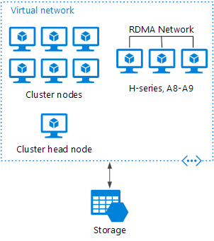
HPC Pack deployed to Azure
In this scenario, the HPC cluster is created entirely within Azure.
The head node provides management and job scheduling services to the cluster. For tightly coupled tasks, use an RDMA network that provides very high bandwidth, low latency communication between VMs. For more information see Deploy an HPC Pack 2016 cluster in Azure.
Burst an HPC cluster to Azure
In this scenario, an organization is running HPC Pack on-premises, and uses Azure VMs for burst capacity. The cluster head node is on-premises. ExpressRoute or VPN Gateway connects the onpremises network to the Azure VNet.

Choose compute and data store technologies
Choose the right technologies for Azure applications.
When designing a solution for Azure, there are two technology choices that you should make early in the design process, because they affect the entire architecture. These are the choice of compute and data store technologies.
Your compute option is which hosting model you choose for the computing resources that your application runs on. Broadly, the choice is between Infrastructure-as-a-Service (IaaS), Platform-asa-Service (PaaS), or Functions-as-a-Service (FaaS), and the spectrum in between. There are seven main compute options currently available in Azure for you to choose from. To make your choice, consider the appropriate features and limitations of the service, availability and scalability, cost, and considerations for DevOps. The comparison tables in this section will help you narrow down your choices.
The data store includes any kind of data your application needs to manage, ingest, generate, or that users create. Business data, caches, IoT data, telemetry, and unstructured log data are the most common types, and applications often contain more than one data type. Different data types have different processing requirements, and so you need to choose the right store for each type for the best results. Some data store technologies support multiple storage models. Use the information in this section to first choose which storage model is best suited for your requirements. Then consider a particular data store within that category, based on factors such as feature set, cost, and ease of management.
This section of the Application Architecture Guide contains the following topics:
- Compute options overview introduces some general considerations for choosing a compute service in Azure.
- Criteria for choosing a compute option compares specific Azure compute services across several axes, including hosting model, DevOps, availability, and scalability.
- Choose the right data store describes the major categories of data store technologies, including RDBMS, key-value store, document database, graph database, and others.
- Comparison criteria for choosing a data store describes some of the factors to consider when choosing a data store.
For more information about these compute options, go to: https://docs.microsoft.com/en-us/ azure/#pivot=services.
Overview of compute options
The term compute refers to the hosting model for the computing resources that your application runs on.
At one end of the spectrum is Intrastructure-as-a-Service (IaaS). With IaaS, you provision the VMs that you need, along with associated network and storage components. Then you deploy whatever software and applications you want onto those VMs. This model is the closest to a traditional onpremises environment, except that Microsoft manages the infrastructure. You still manage the individual VMs.
Platform-as-a-Service (PaaS) provides a managed hosting environment, where you can deploy your application without needing to manage VMs or networking resources. For example, instead of creating individual VMs, you specify an instance count, and the service will provision, configure, and manage the necessary resources. Azure App Service is an example of a PaaS service.
There is a spectrum from IaaS to pure PaaS. For example, Azure VMs can auto-scale by using VM Scale Sets. This automatic scaling capability isn't strictly PaaS, but it's the type of management feature that might be found in a PaaS service.
Functions-as-a-Service (FaaS) goes even further in removing the need to worry about the hosting environment. Instead of creating compute instances and deploying code to those instances, you simply deploy your code, and the service automatically runs it. You don't need to administer the compute resources. These services make use of serverless architecture, and seamlessly scale up or down to whatever level necessary to handle the traffic. Azure Functions are a FaaS service.
IaaS gives the most control, flexibility, and portability. FaaS provides simplicity, elastic scale, and potential cost savings, because you pay only for the time your code is running.
PaaS falls somewhere between the two. In general, the more flexibility a service provides, the more you are responsible for configuring and managing the resources. FaaS services automatically manage nearly all aspects of running an application, while IaaS solutions require you to provision, configure and manage the VMs and network components you create.
Here are the main compute options currently available in Azure:
- Virtual Machines are an IaaS service, allowing you to deploy and manage VMs inside a virtual network (VNet).
- App Service is a managed service for hosting web apps, mobile app back ends, RESTful APIs, or automated business processes.
- Service Fabric is a distributed systems platform that can run in many environments, including Azure or on premises. Service Fabric is an orchestrator of microservices across a cluster of machines.
- Azure Container Service lets you create, configure, and manage a cluster of VMs that are preconfigured to run containerized applications. • Azure Functions is a managed FaaS service.
- Azure Batch is a managed service for running large-scale parallel and high-performance computing (HPC) applications.
- Cloud Services is a managed service for running cloud applications. It uses a PaaS hosting model.
When selecting a compute option, here are some factors to consider:
- Hosting model. How is the service hosted? What requirements and limitations are imposed by this hosting environment?
- DevOps. Is there built-in support for application upgrades? What is the deployment model?
- Scalability. How does the service handle adding or removing instances? Can it auto-scale based on load and other metrics?
- Availability. What is the service SLA?
- Cost. In addition to the cost of the service itself, consider the operations cost for managing a solution built on that service. For example, IaaS solutions might have a higher operations cost.
- What are the overall limitations of each service?
- What kind of application architectures are appropriate for this service?
Compute comparison
The term compute refers to the hosting model for the computing resources that your applications runs on. The following tables compare Azure compute services across several axes. Refer to these tables when selecting a compute option for your application.
Hosting model
Criteria | Virtual Machines | App Service | Service Fabric | Azure Functions | Azure Container Services | Cloud Services | Azure Batch |
Application composition | Agnostic | Applications | Services, guest executables | Functions | Containers | Roles | Scheduled Jobs |
Density | Agnostic | Multiple apps per instance via app plans | Multiple services per VM | No dedicated instances | Multiple containers per VM | One role instance per VM | Multiple containers per VM |
Minimum number of nodes | 1 2 | 1 | 5 3 | No dedicated nodes 1 | 3 | 2 | 1 4 |
State management | Stateless or stateful | Stateless | Stateless or stateful | Stateless | Stateless or stateful | Stateless | Stateless |
Web hosting | Agnostic | Built in | Self-host,IIS in containers | N/A | Agnostic | Built-in (IIS) | No |
OS | Windows, Linux | Windows, Linux (preview) | Windows, Linux (preview) | N/A | Windows, Linux | Windows | Windows, Linux |
Can be deployed to dedicated VNet? | Supported | Supported | Supported | Not supported | Supported | Supported 6 | Supported |
Hybrid Connectivity | Supported | Supported | Supported | Not supported | Supported | Supported 8 | Supported |
Notes:
- If using App Service plan, functions run on the VMs allocated for your App Service plan. For more information, go to https://docs.microsoft.com/en-us/azure/azure-functions/ functions-scale.
- Higher SLA with two or more instances.
- For production environments.
- Can scale down to zero after job completes.
- Requires App Service Environment (ASE).
- Classic VNet only.
- Requires ASE or BizTalk Hybrid Connections.
- Classic VNet, or Resource Manager VNet via VNet peering.
DevOps
Criteria | Virtual Machines | App Service | Service Fabric | Azure Functions | Azure Container Services | Cloud Services | Azure Batch |
Local debugging | Agnostic | IIS Express, others | Local node cluster | AzureFunctions CLI | Local container runtime | Local emulator | Not supported |
Programming model | Agnostic | Web application, Web Jobs for background tasks | Guest executable, Service model, Actor model, Containers | Functions with triggers | Agnostic | Web role, worker role | Command line application |
Resource Manager | Supported | Supported | Supported | Supported | Supported | 2 Limited | Supported |
Application update | No built-in support | Deploymentslots | Rolling upgrade(per service) | No built-in support | Depends on orchestrator. | VIP swap or rolling update | N/A |
Notes:
- Options include IIS Express for ASP.NET or node.js (iisnode); PHP web server; Azure Toolkit for IntelliJ, Azure Toolkit for Eclipse. App Service also supports remote debugging of deployed web app.
- For information, go to https://docs.microsoft.com/en-us/azure/azure-resource-manager/ resource-manager-supported-services.
Scalability
Criteria | Virtual Machines | App Service | Service Fabric | Azure Functions | Azure Container Services | Cloud Services | Azure Batch |
Auto-scaling | VM scale sets | Built-in service | VM scale sets | Built-in service | Not supported | Built-in service | N/A |
Load balancer | Azure load balancer | Integrated | Azure Load Balancer | Integrated | Azure load balancer | Integrated | Azure load balancer |
Scale limit | Platform image: 1000 nodes per VMSS, Custom image: 100 nodes per VMSS | 20 instances, 50 with AppServiceEnvironment | 100 nodes per VMSS | 1 Infinite | 100 | No defined limit, 200 max recommended | 20 core limit by default. Contact customer service for increase. |
Notes:
- For more information, go to https://docs.microsoft.com/en-us/azure/azure-functions/ functions-scale.
Availability
SLA Criteria | Virtual Machines | App Service | Service Fabric | Azure Functions | Azure Container Services | Cloud Services | Azure Batch |
SLA | SLA for Virtual Machines | SLA for App Service | SLA for Service Fabric | SLA for Functions | SLA for Azure Container Service | SLA for Cloud Services | SLA for Azure Batch |
Multiregion failover | Traffic manager | Traffic manager | Traffic manager,Multi-region cluser | Not supported | Traffic manager | Traffic manager | Not Supported |
Notes:
- For more information about speicifc SLAs, go to https://azure.microsoft.com/en-us/ support/legal/sla/.
Security
Criteria | Virtual Machines | App Service | Service Fabric | Azure Functions | Azure Container Services | Cloud Services | Azure Batch |
SSL | Configured in VM | Supported | Supported | Supported | Configured in VM | Supported | Supported |
RBAC | Supported | Supported | Supported | Supported | Supported | Not supported | Supported |
Other
Criteria | Virtual Machines | App Service | Service Fabric | Azure Functions | Azure Container Services | Cloud Services | Azure Batch |
Cost | Windows, Linux | App service pricing | Service fabric pricing | Azure functions pricing | Azure container service pricing | Cloud services pricing | Supported |
Suitable architecture styles | Supported | Supported | Supported | Supported | Microservices, EDA | Web-Queue Worker | Big Compute |
Notes:
- For information about specific cost, go to https://azure.microsoft.com/pricing/details/.
Data store overview
Choose the right data store.
Modern business systems manage increasingly large volumes of data. Data may be ingested from external services, generated by the system itself, or created by users. These data sets may have extremely varied characteristics and processing requirements. Businesses use data to assess trends, trigger business processes, audit their operations, analyze customer behavior, and many other things.
This heterogeneity means that a single data store is usually not the best approach. Instead, it's often better to store different types of data in different data stores, each focused towards a specific workload or usage pattern. The term polyglot persistence is used to describe solutions that use a mix of data store technologies.
Selecting the right data store for your requirements is a key design decision. There are literally hundreds of implementations to choose from among SQL and NoSQL databases. Data stores are often categorized by how they structure data and the types of operations they support. This article describes several of the most common storage models. Note that a particular data store technology may support multiple storage models. For example, a relational database management systems (RDBMS) may also support key/value or graph storage. In fact, there is a general trend for so-called multimodel support, where a single database system supports several models. But it's still useful to understand the different models at a high level.
Not all data stores in a given category provide the same feature-set. Most data stores provide server-side functionality to query and process data. Sometimes this functionality is built into the data storage engine. In other cases, the data storage and processing capabilities are separated, and there may be several options for processing and analysis. Data stores also support different programmatic and management interfaces.
Generally, you should start by considering which storage model is best suited for your requirements. Then consider a particular data store within that category, based on factors such as feature set, cost, and ease of management.
Relational database management systems
Relational databases organize data as a series of two-dimensional tables with rows and columns. Each table has its own columns, and every row in a table has the same set of columns. This model is mathematically based, and most vendors provide a dialect of the Structured Query Language (SQL) for retrieving and managing data. An RDBMS typically implements a transactionally consistent mechanism that conforms to the ACID (Atomic, Consistent, Isolated, Durable) model for updating information.
An RDBMS typically supports a schema-on-write model, where the data structure is defined ahead of time, and all read or write operations must use the schema. This is in contrast to most NoSQL data stores, particularly key/value types, where the schema-on-read model assumes that the client will be imposing its own interpretive schema on data coming out of the database, and is agnostic to the data format being written.
An RDBMS is very useful when strong consistency guarantees are important — where all changes are atomic, and transactions always leave the data in a consistent state. However, the underlying structures do not lend themselves to scaling out by distributing storage and processing across machines. Also, information stored in an RDBMS, must be put into a relational structure by following the normalization process. While this process is well understood, it can lead to inefficiencies, because of the need to disassemble logical entities into rows in separate tables, and then reassemble the data when running queries.
Relevant Azure service:
- Azure SQL Database. For information, go to https://azure.microsoft.com/services/sql-database.
- Azure Database for MySQL. For information, go to https://azure.microsoft.com/services/mysql.
- Azure Database for PostgreSQL. For information, go to https://azure.microsoft.com/services/ postgresql.
Key/value stores
A key/value store is essentially a large hash table. You associate each data value with a unique key, and the key/value store uses this key to store the data by using an appropriate hashing function. The hashing function is selected to provide an even distribution of hashed keys across the data storage.
Most key/value stores only support simple query, insert, and delete operations. To modify a value (either partially or completely), an application must overwrite the existing data for the entire value. In most implementations, reading or writing a single value is an atomic operation. If the value is large, writing may take some time.
An application can store arbitrary data as a set of values, although some key/value stores impose limits on the maximum size of values. The stored values are opaque to the storage system software. Any schema information must be provided and interpreted by the application. Essentially, values are blobs and the key/ value store simply retrieves or stores the value by key.

Key/value stores are highly optimized for applications performing simple lookups, but are less suitable for systems that need to query data across different key/value stores. Key/value stores are also not optimized for scenarios where querying by value is important, rather than performing lookups based only on keys. For example, with a relational database, you can find a record by using a WHERE clause, but key/values stores usually do not have this type of lookup capability for values.
A single key/value store can be extremely scalable, as the data store can easily distribute data across multiple nodes on separate machines.
Relevant Azure services:
- Cosmos DB. For information, go to https://azure.microsoft.com/services/cosmos-db.
- Azure Redis Cache. For information, go to https://azure.microsoft.com/services/cache.
Document databases
A document database is conceptually similar to a key/value store, except that it stores a collection of named fields and data (known as documents), each of which could be simple scalar items or compound elements such as lists and child collections. The data in the fields of a document can be encoded in a variety of ways, including XML, YAML, JSON, BSON,or even stored as plain text. Unlike key/value stores, the fields in documents are exposed to the storage management system, enabling an application to query and filter data by using the values in these fields.
Typically, a document contains the entire data for an entity. What items constitute an entity are application specific. For example, an entity could contain the details of a customer, an order, or a combination of both. A single document may contain information that would be spread across several relational tables in an RDBMS.
A document store does not require that all documents have the same structure. This free-form approach provides a great deal of flexibility. Applications can store different data in documents as business requirements change.
The application can retrieve documents by using the document key. This is a unique identifier for the document, which is often hashed, to help distribute data evenly. Some document databases create the document key automatically. Others enable you to specify an attribute of the document to use as the key. The application can also query documents based on the value of one or more fields. Some document databases support indexing to facilitate fast lookup of documents based on one or more indexed fields.

Many document databases support in-place updates, enabling an application to modify the values of specific fields in a document without rewriting the entire document. Read and write operations over multiple fields in a single document are usually atomic.
Relevant Azure service: Cosmos DB
Graph databases
A graph database stores two types of information, nodes and edges. You can think of nodes as entities. Edges which specify the relationships between nodes. Both nodes and edges can have properties that provide information about that node or edge, similar to columns in a table. Edges can also have a direction indicating the nature of the relationship.
The purpose of a graph database is to allow an application to efficiently perform queries that traverse the network of nodes and edges, and to analyze the relationships between entities. The follow diagram shows an organization's personnel database structured as a graph. The entities are employees and departments, and the edges indicate reporting relationships and the department in which employees work. In this graph, the arrows on the edges show the direction of the relationships.

This structure makes it straightforward to perform queries such as "Find all employees who report directly or indirectly to Sarah" or "Who works in the same department as John?" For large graphs with lots of entities and relationships, you can perform very complex analyses very quickly. Many graph databases provide a query language that you can use to traverse a network of relationships efficiently.
Relevant Azure service: Cosmos DB. For information, go to https://azure.microsoft.com/services/ cosmos-db
Column-family databases
A column-family database organizes data into rows and columns. In its simplest form, a columnfamily database can appear very similar to a relational database, at least conceptually. The real power of a column-family database lies in its denormalized approach to structuring sparse data.
You can think of a column-family database as holding tabular data with rows and columns, but the columns are divided into groups known as column families. Each column family holds a set of columns that are logically related together and are typically retrieved or manipulated as a unit. Other data that is accessed separately can be stored in separate column families. Within a column family, new columns can be added dynamically, and rows can be sparse (that is, a row doesn't need to have a value for every column).

The following diagram shows an example with two column families, Identity and Contact Info. The data for a single entity has the same row key in each column-family. This structure, where the rows for any given object in a column family can vary dynamically, is an important benefit of the columnfamily approach, making this form of data store highly suited for storing structured, volatile data. Unlike a key/value store or a document database, most column-family databases store data in key order, rather than by computing a hash. Many implementations allow you to create indexes over specific columns in a column-family. Indexes let you retrieve data by columns value, rather than row key.
Read and write operations for a row are usually atomic with a single column-family, although some implementations provide atomicity across the entire row, spanning multiple column-families.
Relevant Azure service: HBase in HDInsight. For information, go to https://azure.microsoft.com/ services/cosmos-db
Data analytics
Data analytics stores provide massively parallel solutions for ingesting, storing, and analyzing data. This data is distributed across multiple servers using a share-nothing architecture to maximize scalability and minimize dependencies. The data is unlikely to be static, so these stores must be able to handle large quantities of information, arriving in a variety of formats from multiple streams, while continuing to process new queries.
Relevant Azure services:
- SQL Data Warehouse
- Azure Data Lake
Search Engine Databases
A search engine database supports the ability to search for information held in external data stores and services. A search engine database can be used to index massive volumes of data and provide near real-time access to these indexes. Although search engine databases are commonly thought of as being synonymous with the web, many large-scale systems use them to provide structured and ad-hoc search capabilities on top of their own databases.
The key characteristics of a search engine database are the ability to store and index information very quickly, and provide fast response times for search requests. Indexes can be multi-dimensional and may support free-text searches across large volumes of text data. Indexing can be performed using a pull model, triggered by the search engine database, or using a push model, initiated by external application code.
Searching can be exact or fuzzy. A fuzzy search finds documents that match a set of terms and calculates how closely they match. Some search engines also support linguistic analysis that can return matches based on synonyms, genre expansions (for example, matching dogs to pets), and stemming (matching words with the same root).
Relevant Azure service: Azure Search
Time Series Databases
Time series data is a set of values organized by time, and a time series database is a database that is optimized for this type of data. Time series databases must support a very high number of writes, as they typically collect large amounts of data in real time from a large number of sources. Updates are rare, and deletes are often done as bulk operations. Although the records written to a time-series database are generally small, there are often a large number of records, and total data size can grow rapidly.
Time series databases are good for storing telemetry data. Scenarios include IoT sensors or application/system counters.
Relevant Azure service: Time Series Insights
Object storage
Object storage is optimized for storing and retrieving large binary objects (images, files, video and audio streams, large application data objects and documents, virtual machine disk images). Objects in these store types are composed of the stored data, some metadata, and a unique ID for accessing the object. Object stores enables the management of extremely large amounts of unstructured data. Relevant Azure service: Blob Storage
Shared files
Sometimes, using simple flat files can be the most effective means of storing and retrieving information. Using file shares enables files to be accessed across a network. Given appropriate security and concurrent access control mechanisms, sharing data in this way can enable distributed services to provide highly scalable data access for performing basic, low-level operations such as simple read and write requests.
Relevant Azure service: File Storage
Data store comparison
Criteria for choosing a data store
Azure supports many types of data storage solutions, each providing different features and capabilities. This article describes the comparison criteria you should use when evaluating a data store. The goal is to help you determine which data storage types can meet your solution's requirements.
General Considerations
To start your comparison, gather as much of the following information as you can about your data needs. This information will help you to determine which data storage types will meet your needs.
Functional requirements
- Data format. What type of data are you intending to store? Common types include transactional data, JSON objects, telemetry, search indexes, or flat files.
- Data size. How large are the entities you need to store? Will these entities need to be maintained as a single document, or can they be split across multiple documents, tables, collections, and so forth?
- Scale and structure. What is the overall amount of storage capacity you need? Do you anticipate partitioning your data?
- Data relationships. Will your data need to support one-to-many or many-to-many relationships? Are relationships themselves an important part of the data? Will you need to join or otherwise combine data from within the same dataset, or from external datasets?
- Consistency model. How important is it for updates made in one node to appear in other nodes, before further changes can be made? Can you accept eventual consistency? Do you need ACID guarantees for transactions?
- Schema flexibility. What kind of schemas will you apply to your data? Will you use a fixed schema, a schema-on-write approach, or a schema-on-read approach?
- Concurrency. What kind of concurrency mechanism do you want to use when updating and synchronizing data? Will the application perform many updates that could potentially conflict. If so, you may requiring record locking and pessimistic concurrency control. Alternatively, can you support optimistic concurrency controls? If so, is simple timestamp-based concurrency control enough, or do you need the added functionality of multi-version concurrency control?
- Data movement. Will your solution need to perform ETL tasks to move data to other stores or data warehouses?
- Data lifecycle. Is the data write-once, read-many? Can it be moved into cool or cold storage?
- Other supported features. Do you need any other specific features, such as schema validation, aggregation, indexing, full-text search, MapReduce, or other query capabilities?
Non-functional requirements
- Performance and scalability. What are your data performance requirements? Do you have specific requirements for data ingestion rates and data processing rates? What are the acceptable response times for querying and aggregation of data once ingested? How large will you need the data store to scale up? Is your workload more read-heavy or write-heavy?
- Reliability. What overall SLA do you need to support? What level of fault-tolerance do you need to provide for data consumers? What kind of backup and restore capabilities do you need?
- Replication. Will your data need to be distributed among multiple replicas or regions? What kind of data replication capabilities do you require?
- Limits. Will the limits of a particular data store support your requirements for scale, number of connections, and throughput?
Management and cost
- Managed service. When possible, use a managed data service, unless you require specific capabilities that can only be found in an IaaS-hosted data store.
- Region availability. For managed services, is the service available in all Azure regions? Does your solution need to be hosted in certain Azure regions?
- Portability. Will your data need to migrated to on-premises, external datacenters, or other cloud hosting environments?
- Licensing. Do you have a preference of a proprietary versus OSS license type? Are there any other external restrictions on what type of license you can use?
- Overall cost. What is the overall cost of using the service within your solution? How many instances will need to run, to support your uptime and throughput requirements? Consider operations costs in this calculation. One reason to prefer managed services is the reduced operational cost.
- Cost effectiveness. Can you partition your data, to store it more cost effectively? For example, can you move large objects out of an expensive relational database into an object store?
Security
- Security. What type of encryption do you require? Do you need encryption at rest? What authentication mechanism do you want to use to connect to your data?
- Auditing. What kind of audit log do you need to generate?
- Networking requirements. Do you need to restrict or otherwise manage access to your data from other network resources? Does data need to be accessible only from inside the Azure environment? Does the data need to be accessible from specific IP addresses or subnets? Does it need to be accessible from applications or services hosted on-premises or in other external datacenters?
DevOps
- Skill set. Are there particular programming languages, operating systems, or other technology that your team is particularly adept at using? Are there others that would be difficult for your team to work with?
- Clients. Is there good client support for your development languages?
The following sections compare various data store models in terms of workload profile, data types, and example use cases.
Relational database management systems (RDBMS)
Workload
- Both the creation of new records and updates to existing data happen regularly.
- Multiple operations have to be completed in a single transaction.
- Requires aggregation functions to perform cross-tabulation.
- Strong integration with reporting tools is required.
- Relationships are enforced using database constraints.
- Indexes are used to optimize query performance.
- Allows access to specific subsets of data.
Data type
- Data is highly normalized.
- Database schemas are required and enforced.
- Many-to-many relationships between data entities in the database.
- Constraints are defined in the schema and imposed on any data in the database.
- Data requires high integrity. Indexes and relationships need to be maintained accurately.
- Data requires strong consistency. Transactions operate in a way that ensures all data are 100% consistent for all users and processes.
- Size of individual data entries is intended to be small to medium-sized.
Examples
- Line of business (human capital management, customer relationship management, enterprise resource planning)
- Inventory management
- Reporting database
- Accounting
- Asset management
- Fund management
- Order management
Document databases
Workload
- General purpose.
- Insert and update operations are common. Both the creation of new records and updates to existing data happen regularly.
- No object-relational impedance mismatch. Documents can better match the object structures used in application code.
- Optimistic concurrency is more commonly used.
- Data must be modified and processed by consuming application.
- Data requires index on multiple fields.
- Individual documents are retrieved and written as a single block.
Data type
- Data can be managed in de-normalized way.
- Size of individual document data is relatively small.
- Each document type can use its own schema.
- Documents can include optional fields.
- Document data is semi-structured, meaning that data types of each field are not strictly defined.
- Data aggregation is supported.
Examples
- Product catalog
- User accounts
- Bill of materials
- Personalization
- Content management
- Operations data
- Inventory management
- Transaction history data
- Materialized view of other NoSQL stores. Replaces file/BLOB indexing.
Key/value stores
Workload
- Data is identified and accessed using a single ID key, like a dictionary.
- Massively scalable.
- No joins, lock, or unions are required.
- No aggregation mechanisms are used.
- Secondary indexes are generally not used.
Data type
- Data size tends to be large.
- Each key is associated with a single value, which is an unmanaged data BLOB.
- There is no schema enforcement.
- No relationships between entities.
Examples
- Data caching
- Session management
- User preference and profile management
- Product recommendation and ad serving
- Dictionaries
Graph databases
Workload
- The relationships between data items are very complex, involving many hops between related data items.
- The relationship between data items are dynamic and change over time.
- Relationships between objects are first-class citizens, without requiring foreign-keys and joins to traverse.
Data type
- Data is comprised of nodes and relationships.
- Nodes are similar to table rows or JSON documents.
- Relationships are just as important as nodes, and are exposed directly in the query language.
- Composite objects, such as a person with multiple phone numbers, tend to be broken into separate, smaller nodes, combined with traversable relationships.
Examples
- Organization charts
- Social graphs
- Fraud detection
- Analytics
- Recommendation engines
Column-family databases
Workload
- Most column-family databases perform write operations extremely quickly.
- Update and delete operations are rare.
- Designed to provide high throughput and low-latency access.
- Supports easy query access to a particular set of fields within a much larger record.
- Massively scalable.
Data type
- Data is stored in tables consisting of a key column and one or more column families.
- Specific columns can vary by individual rows.
- Individual cells are accessed via get and put commands
- Multiple rows are returned using a scan command.
Examples
- Recommendations
- Personalization
- Sensor data
- Telemetry
- Messaging
- Social media analytics
- Web analytics
- Activity monitoring
- Weather and other time-series data
Search engine databases
Workload
- Indexing data from multiple sources and services.
- Queries are ad-hoc and can be complex.
- Requires aggregation.
- Full text search is required.
- Ad hoc self-service query is required.
- Data analysis with index on all fields is required.
Data type
- Semi-structured or unstructured
- Text
- Text with reference to structured data
Examples
- Product catalogs
- Site search
- Logging
- Analytics
- Shopping sites
Data warehouse
Workload
- Data analytics
- Enterprise BI
Data type
- Historical data from multiple sources.
- Usually denormalized in a "star" or "snowflake" schema, consisting of fact and dimension tables.
- Usually loaded with new data on a scheduled basis.
- Dimension tables often include multiple historic versions of an entity, referred to as a slowly changing dimension.
Examples
- An enterprise data warehouse that provides data for analytical models, reports, and dashboards.
Time series databases
Workload
- An overwhelmingly proportion of operations (95-99%) are writes.
- Records are generally appended sequentially in time order.
- Updates are rare.
- Deletes occur in bulk, and are made to contiguous blocks or records.
- Read requests can be larger than available memory.
- It's common for multiple reads to occur simultaneously.
- Data is read sequentially in either ascending or descending time order.
Data type
- A time stamp that is used as the primary key and sorting mechanism.
- Measurements from the entry or descriptions of what the entry represents.
- Tags that define additional information about the type, origin, and other information about the entry.
Examples
- Monitoring and event telemetry.
- Sensor or other IoT data.
Object storage
Workload
- Identified by key.
- Objects may be publicly or privately accessible.
- Content is typically an asset such as a spreadsheet, image, or video file.
- Content must be durable (persistent), and external to any application tier or virtual machine.
Data type
- Data size is large.
- Blob data.
- Value is opaque.
Examples
- Images, videos, office documents, PDFs
- CSS, Scripts, CSV
- Static HTML, JSON
- Log and audit files
- Database backups
Shared files
Workload
- Migration from existing apps that interact with the file system.
- Requires SMB interface.
Data type
- Files in a hierarchical set of folders.
- Accessible with standard I/O libraries.
Examples
- Legacy files.
- Shared content accessible among a number of VMs or app instances.
Design your Azure application: design principles
Now that you have chosen your architecture and your compute and data store technologies, you are ready to start designing and building your cloud application. This section and the two following it provide guidance and resources for optimal application design for the cloud.
This section describes ten design principles to keep in mind as you build. Following these principles will help you build an application that is more scalable, resilient, and manageable.
- Design for self healing. In a distributed system, failures happen. Design your application to be self healing when failures occur.
- Make all things redundant. Build redundancy into your application, to avoid having single points of failure.
- Minimize coordination. Minimize coordination between application services to achieve scalability.
- Design to scale out. Design your application so that it can scale horizontally, adding or removing new instances as demand requires.
- Partition around limits. Use partitioning to work around database, network, and compute limits.
- Design for operations. Design your application so that the operations team has the tools they need.
- Use managed services. When possible, use platform as a service (PaaS) rather than infrastructure as a service (IaaS).
- Use the best data store for the job. Pick the storage technology that is the best fit for your data and how it will be used.
- Design for evolution. All successful applications change over time. An evolutionary design is key for continuous innovation.
- Build for the needs of business. Every design decision must be justified by a business requirement.
Design for self healing
Design your application to be self healing when failures occur
In a distributed system, failures happen. Hardware can fail. The network can have transient failures.
Rarely, an entire service or region may experience a disruption, but even those must be planned for.
Therefore, design an application to be self healing when failures occur. This requires a three-pronged approach:
- Detect failures.
- Respond to failures gracefully.
- Log and monitor failures, to give operational insight.
How you respond to a particular type of failure may depend on your application's availability requirements. For example, if you require very high availability, you might automatically fail over to a secondary region during a regional outage. However, that will incur a higher cost than a singleregion deployment.
Also, don't just consider big events like regional outages, which are generally rare. You should focus as much, if not more, on handling local, short-lived failures, such as network connectivity failures or failed database connections.
Recommendations
Retry failed operations. Transient failures may occur due to momentary loss of network connectivity, a dropped database connection, or a timeout when a service is busy. Build retry logic into your application to handle transient failures. For many Azure services, the client SDK implements automatic retries. For more information, see Retry Pattern, and go to https://docs.microsoft.com/enus/azure/architecture/best-practices/transient-faults.
Protect failing remote services (Circuit Breaker). It's good to retry after a transient failure, but if the failure persists, you can end up with too many callers hammering a failing service. This can lead to cascading failures, as requests back up. Use the Circuit Breaker Pattern to fail fast (without making the remote call) when an operation is likely to fail.
Isolate critical resources (Bulkhead). Failures in one subsystem can sometimes cascade. This can happen if a failure causes some resources, such as threads or sockets, not to get freed in a timely manner, leading to resource exhaustion. To avoid this, partition a system into isolated groups, so that a failure in one partition does not bring down the entire system.
Perform load leveling. Applications may experience sudden spikes in traffic that can overwhelm services on the backend. To avoid this, use the Queue-Based Load Leveling Pattern to queue work items to run asynchronously. The queue acts as a buffer that smooths out peaks in the load.
Fail over. If an instance can't be reached, fail over to another instance. For things that are stateless, like a web server, put several instances behind a load balancer or traffic manager. For things that store state, like a database, use replicas and fail over. Depending on the data store and how it replicates, this may require the application to deal with eventual consistency.
Compensate failed transactions. In general, avoid distributed transactions, as they require coordination across services and resources. Instead, compose an operation from smaller individual transactions. If the operation fails midway through, use Compensating Transactions to undo any step that already completed.
Checkpoint long-running transactions. Checkpoints can provide resiliency if a long-running operation fails. When the operation restarts (for example, it is picked up by another VM), it can be resumed from the last checkpoint.
Degrade gracefully. Sometimes you can't work around a problem, but you can provide reduced functionality that is still useful. Consider an application that shows a catalog of books. If the application can't retrieve the thumbnail image for the cover, it might show a placeholder image. Entire subsystems might be noncritical for the application. For example, in an e-commerce site, showing product recommendations is probably less critical than processing orders.
Throttle clients. Sometimes a small number of users create excessive load, which can reduce your application's availability for other users. In this situation, throttle the client for a certain period of time. See Throttling Pattern.
Block bad actors. Just because you throttle a client, it doesn't mean the client was acting maliciously. It just means the client exceeded their service quota. But if a client consistently exceeds their quota or otherwise behaves badly, you might block them. Define an out-of-band process for user to request getting unblocked.
Use leader election. When you need to coordinate a task, use Leader Election to select a coordinator. That way, the coordinator is not a single point of failure. If the coordinator fails, a new one is selected. Rather than implement a leader election algorithm from scratch, consider an off-theshelf solution such as Zookeeper.
Test with fault injection. All too often, the success path is well tested but not the failure path. A system could run in production for a long time before a failure path is exercised. Use fault injection to test the resiliency of the system to failures, either by triggering actual failures or by simulating them.
Embrace chaos engineering. Chaos engineering extends the notion of fault injection, by randomly injecting failures or abnormal conditions into production instances.
For a structured approach to making your applications self healing, see Design resilient applications for Azure.
Make all things redundant
Build redundancy into your application, to avoid having single points of failure
A resilient application routes around failure. Identify the critical paths in your application. Is there redundancy at each point in the path? If a subsystem fails, will the application fail over to something else?
Recommendations
Consider business requirements. The amount of redundancy built into a system can affect both cost and complexity. Your architecture should be informed by your business requirements, such as recovery time objective (RTO). For example, a multi-region deployment is more expensive than a single-region deployment, and is more complicated to manage. You will need operational procedures to handle failover and failback. The additional cost and complexity might be justified for some business scenarios and not others.

Place VMs behind a load balancer. Don't use a single VM for mission-critical workloads. Instead, place multiple VMs behind a load balancer. If any VM becomes unavailable, the load balancer distributes traffic to the remaining healthy VMs. To learn how to deploy this configuration, see Multiple VMs for scalability and availability.
Replicate databases. Azure SQL Database and Cosmos DB automatically replicate the data within a region, and you can enable geo-replication across regions. If you are using an IaaS database solution, choose one that supports replication and failover, such as SQL Server Always On Availability Groups. For information, go to https://docs.microsoft.com/en-us/sql/database-engine/availability-groups/ windows/always-on-availability-groups-sql-server.
Enable geo-replication. Geo-replication for Azure SQL Database and Cosmos DB creates secondary readable replicas of your data in one or more secondary regions. In the event of an outage, the database can fail over to the secondary region for writes. For more information about Azure SQL database, go to https://docs.microsoft.com/en-us/azure/sql-database/sql-database-geo-replicationoverview. For more information about Cosmos DB, go to https://docs.microsoft.com/en-us/azure/ documentdb/documentdb-distribute-data-globally.
Partition for availability. Database partitioning is often used to improve scalability, but it can also improve availability. If one shard goes down, the other shards can still be reached. A failure in one shard will only disrupt a subset of the total transactions.
Deploy to more than one region. For the highest availability, deploy the application to more than one region. That way, in the rare case when a problem affects an entire region, the application can fail over to another region. The following diagram shows a multi-region application that uses Azure Traffic Manager to handle failover.

Synchronize front and backend failover. Use Azure Traffic Manager to fail over the front end. If the front end becomes unreachable in one region, Traffic Manager will route new requests to the secondary region. Depending on your database solution, you may need to coordinate failing over the database.
Use automatic failover but manual failback. Use Traffic Manager for automatic failover, but not for automatic failback. Automatic failback carries a risk that you might switch to the primary region before the region is completely healthy. Instead, verify that all application subsystems are healthy before manually failing back. Also, depending on the database, you might need to check data consistency before failing back.
Include redundancy for Traffic Manager. Traffic Manager is a possible failure point. Review the Traffic Manager SLA, and determine whether using Traffic Manager alone meets your business requirements for high availability. If not, consider adding another traffic management solution as a failback. If the Azure Traffic Manager service fails, change your CNAME records in DNS to point to the other traffic management service.
Minimize coordination
Minimize coordination between application services to achieve scalability.
Most cloud applications consist of multiple application services — web front ends, databases, business processes, reporting and analysis, and so on. To achieve scalability and reliability, each of those services should run on multiple instances.
What happens when two instances try to perform concurrent operations that affect some shared state? In some cases, there must be coordination across nodes, for example to preserve ACID guarantees. In this diagram, Node2 is waiting for Node1 to release a database lock:

Coordination limits the benefits of horizontal scale and creates bottlenecks. In this example, as you scale out the application and add more instances, you'll see increased lock contention. In the worst case, the front-end instances will spend most of their time waiting on locks. "Exactly once" semantics are another frequent source of coordination. For example, an order must be processed exactly once. Two workers are listening for new orders. Worker1 picks up an order for processing. The application must ensure that Worker2 doesn't duplicate the work, but also if Worker1 crashes, the order isn't dropped.

You can use a pattern such as Scheduler Agent Supervisor to coordinate between the workers, but in this case a better approach might be to partition the work. Each worker is assigned a certain range of orders (say, by billing region). If a worker crashes, a new instance picks up where the previous instance left off, but multiple instances aren't contending.
Recommendations
Embrace eventual consistency. When data is distributed, it takes coordination to enforce strong consistency guarantees. For example, suppose an operation updates two databases. Instead of putting it into a single transaction scope, it's better if the system can accommodate eventual consistency, perhaps by using the Compensating Transaction pattern to logically roll back after a failure.
Use domain events to synchronize state. A domain event is an event that records when something happens that has significance within the domain. Interested services can listen for the event, rather than using a global transaction to coordinate across multiple services. If this approach is used, the system must tolerate eventual consistency (see previous item).
Consider patterns such as CQRS and event sourcing. These two patterns can help to reduce contention between read workloads and write workloads.
- The CQRS pattern separates read operations from write operations. In some implementations, the read data is physically separated from the write data.
- In the Event Sourcing pattern, state changes are recorded as a series of events to an append-only data store. Appending an event to the stream is an atomic operation, requiring minimal locking.
These two patterns complement each other. If the write-only store in CQRS uses event sourcing, the read-only store can listen for the same events to create a readable snapshot of the current state, optimized for queries. Before adopting CQRS or event sourcing, however, be aware of the challenges of this approach. For more information, see CQRS architecture style.
Partition data. Avoid putting all of your data into one data schema that is shared across many application services. A microservices architecture enforces this principle by making each service responsible for its own data store. Within a single database, partitioning the data into shards can improve concurrency, because a service writing to one shard does not affect a service writing to a different shard.
Design idempotent operations. When possible, design operations to be idempotent. That way, they can be handled using at-least-once semantics. For example, you can put work items on a queue. If a worker crashes in the middle of an operation, another worker simply picks up the work item.
Use asynchronous parallel processing. If an operation requires multiple steps that are performed asynchronously (such as remote service calls), you might be able to call them in parallel, and then aggregate the results. This approach assumes that each step does not depend on the results of the previous step.
Use optimistic concurrency when possible. Pessimistic concurrency control uses database locks to prevent conflicts. This can cause poor performance and reduce availability. With optimistic concurrency control, each transaction modifies a copy or snapshot of the data. When the transaction is committed, the database engine validates the transaction and rejects any transactions that would affect database consistency.
Azure SQL Database and SQL Server support optimistic concurrency through snapshot isolation. For more information, go to https://docs.microsoft.com/en-us/sql/t-sql/statements/set-transactionisolation-level-transact-sql. Some Azure storage services support optimistic concurrency through the use of Etags, including DocumentDB API and Azure Storage. For more information about DocumentDB API, go to https://docs.microsoft.com/en-us/azure/documentdb/documentdb-faq. For more information about Azure Storage, go to https://azure.microsoft.com/blog/managingconcurrency-in-microsoft-azure-storage-2/
Consider MapReduce or other parallel, distributed algorithms. Depending on the data and type of work to be performed, you may be able to split the work into independent tasks that can be performed by multiple nodes working in parallel. See Big Compute Architecture Style.
Use leader election for coordination. In cases where you need to coordinate operations, make sure the coordinator does not become a single point of failure in the application. Using the Leader Election pattern, one instance is the leader at any time, and acts as the coordinator. If the leader fails, a new instance is elected to be the leader.
Design to scale out
Design your application so that it can scale horizontally
A primary advantage of the cloud is elastic scaling — the ability to use as much capacity as you need, scaling out as load increases, and scaling in when the extra capacity is not needed. Design your application so that it can scale horizontally, adding or removing new instances as demand requires.
Recommendations
Avoid instance stickiness. Stickiness, or session affinity, is when requests from the same client are always routed to the same server. Stickiness limits the application's ability to scale out. For example, traffic from a high-volume user will not be distributed across instances. Causes of stickiness include storing session state in memory, and using machine-specific keys for encryption. Make sure that any instance can handle any request.
Identify bottlenecks. Scaling out isn't a magic fix for every performance issue. For example, if your backend database is the bottleneck, it won't help to add more web servers. Identify and resolve the bottlenecks in the system first, before throwing more instances at the problem. Stateful parts of the system are the most likely cause of bottlenecks.
Decompose workloads by scalability requirements. Applications often consist of multiple workloads, with different requirements for scaling. For example, an application might have a publicfacing site and a separate administration site. The public site may experience sudden surges in traffic, while the administration site has a smaller, more predictable load.
Offload resource-intensive tasks. Tasks that require a lot of CPU or I/O resources should be moved to background jobs when possible, to minimize the load on the front end that is handling user requests.
Use built-in autoscaling features. Many Azure compute services have built-in support for autoscaling. If the application has a predictable, regular workload, scale out on a schedule. For example, scale out during business hours. Otherwise, if the workload is not predictable, use performance metrics such as CPU or request queue length to trigger autoscaling. For autoscaling best practices, see Autoscaling. For autoscaling best practices, go to https://docs.microsoft.com/enus/azure/architecture/best-practices/auto-scaling.
Consider aggressive autoscaling for critical workloads. For critical workloads, you want to keep ahead of demand. It's better to add new instances quickly under heavy load to handle the additional traffic, and then gradually scale back.
Design for scale in. Remember that with elastic scale, the application will have periods of scale in, when instances get removed. The application must gracefully handle instances being removed. Here are some ways to handle scalein:
- Listen for shutdown events (when available) and shut down cleanly.
- Clients/consumers of a service should support transient fault handling and retry.
- For long-running tasks, consider breaking up the work, using checkpoints or the Pipes and Filters pattern.
- Put work items on a queue so that another instance can pick up the work, if an instance is removed in the middle of processing.
Partition around limits
Use Partitioning to work around database, network, and compute limits.
A primary advantage of the cloud is elastic scaling — the ability to use as much capacity as you need, scaling out as load increases, and scaling in when the extra capacity is not needed. Design your application so that it can scale horizontally, adding or removing new instances as demand requires.
In the cloud, all services have limits in their ability to scale up. Azure service limits are documented in Azure subscription and service limits, quotas, and constraints. Limits include number of cores, database size, query throughput, and network throughput. If your system grows sufficiently large, you may hit one or more of these limits. Use partitioning to work around these limits.
There are many ways to partition a system, such as:
- Partition a database to avoid limits on database size, data I/O, or number of concurrent sessions.
- Partition a queue or message bus to avoid limits on the number of requests or the number of concurrent connections.
- Partition an App Service web app to avoid limits on the number of instances per App Service plan.
A database can be partitioned horizontally, vertically, or functionally.
- In horizontal partitioning, also called sharding, each partition holds data for a subset of the total data set. The partitions share the same data schema. For example, customers whose names start with A–M go into one partition, N–Z into another partition.
- In vertical partitioning, each partition holds a subset of the fields for the items in the data store. For example, put frequently accessed fields in one partition, and less frequently accessed fields in another.
- In functional partitioning, data is partitioned according to how it is used by each bounded context in the system. For example, store invoice data in one partition and product inventory data in another. The schemas are independent.
For more information, go to https://docs.microsoft.com/en-us/azure/architecture/best-practices/ data-partitioning.
Recommendations
Partition different parts of the application. Databases are one obvious candidate for partitioning, but also consider storage, cache, queues, and compute instances.
Design the partition key to avoid hot spots. If you partition a database, but one shard still gets the majority of the requests, then you haven't solved your problem. Ideally, load gets distributed evenly across all the partitions. For example, hash by customer ID and not the first letter of the customer name, because some letters are more frequent. The same principle applies when partitioning a message queue. Pick a partition key that leads to an even distribution of messages across the set of queues. For more information, see Sharding.
Partition around Azure subscription and service limits. Individual components and services have limits, but there are also limits for subscriptions and resource groups. For very large applications, you might need to partition around those limits.
Partition at different levels. Consider a database server deployed on a VM. The VM has a VHD that is backed by Azure Storage. The storage account belongs to an Azure subscription. Notice that each step in the hierarchy has limits. The database server may have a connection pool limit. VMs have CPU and network limits. Storage has IOPS limits. The subscription has limits on the number of VM cores. Generally, it's easier to partition lower in the hierarchy. Only large applications should need to partition at the subscription level.
Design for operations
Design an application so that the operations team has the tools they need.
The cloud has dramatically changed the role of the operations team. They are no longer responsible for managing the hardware and infrastructure that hosts the application. That said, operations is still a critical part of running a successful cloud application. Some of the important functions of the operations team include:
- Deployment
- Monitoring
- Escalation
- Incident response
- Security auditing
Robust logging and tracing are particularly important in cloud applications. Involve the operations team in design and planning, to ensure the application gives them the data and insight thay need to be successful.
Recommendations
Make all things observable. Once a solution is deployed and running, logs and traces are your primary insight into the system. Tracing records a path through the system, and is useful to pinpoint bottlenecks, performance issues, and failure points. Logging captures individual events such as application state changes, errors, and exceptions. Log in production, or else you lose insight at the very times when you need it the most.
Instrument for monitoring. Monitoring gives insight into how well (or poorly) an application is performing, in terms of availability, performance, and system health. For example, monitoring tells you whether you are meeting your SLA. Monitoring happens during the normal operation of the system. It should be as close to real-time as possible, so that the operations staff can react to issues quickly. Ideally, monitoring can help avert problems before they lead to a critical failure. For more information, go to https://docs.microsoft.com/en-us/azure/architecture/best-practices/monitoring.
Instrument for root cause analysis. Root cause analysis is the process of finding the underlying cause of failures. It occurs after a failure has already happened.
Use distributed tracing. Use a distributed tracing system that is designed for concurrency, asynchrony, and cloud scale. Traces should include a correlation ID that flows across service boundaries. A single operation may involve calls to multiple application services. If an operation fails, the correlation ID helps to pinpoint the cause of the failure.
Standardize logs and metrics. The operations team will need to aggregate logs from across the various services in your solution. If every service uses its own logging format, it becomes difficult or impossible to get useful information from them. Define a common schema that includes fields such as correlation ID, event name, IP address of the sender, and so forth. Individual services can derive custom schemas that inherit the base schema and contain additional fields.
Automate management tasks. Including provisioning, deployment, and monitoring. Automating a task makes it repeatable and less prone to human errors.
Treat configuration as code. Check configuration files into a version control system, so that you can track and version your changes, and roll back if needed.
Use managed services
When possible, use platform as a service (PaaS) rather than infrastructure as a service (IaaS).
IaaS is like having a box of parts. You can build anything, but you have to assemble it yourself.
Managed services are easier to configure and administer. You don't need to provision VMs, set up VNets, manage patches and updates, and all of the other overhead associated with running software on a VM.
For example, suppose your application needs a message queue. You could set up your own messaging service on a VM, using something like RabbitMQ. But Azure Service Bus already provides reliable messaging as service, and it's simpler to set up. Just create a Service Bus namespace (which can be done as part of a deployment script) and then call Service Bus using the client SDK.
Of course, your application may have specific requirements that make an IaaS approach more suitable. However, even if your application is based on IaaS, look for places where it may be natural to incorporate managed services. These include cache, queues, and data storage.
Instead of running...
- Active Directory
- Elasticsearch
- Hadoop
- IIS
- Mongo DBC
- Redis
- SQL Server
Consider using…
- Azure Active Directory Domain Services
- Azure Search
- HDInsight
- App Service
- Cosmos DB
- Azure Redis Cache
- Azure SQL Database
Use the best data store for the job
Pick the storage technology that is the best fit for your data and how it will be used.
IaaS is like having a box of parts. You can build anything, but you have to assemble it yourself.
Managed services are easier to configure and administer. You don't need to provision VMs, set up VNets, manage patches and updates, and all of the other overhead associated with running software on a VM.
For example, suppose your application needs a message queue. You could set up your own messaging service on a VM, using something like RabbitMQ. But Azure Service Bus already provides reliable messaging as service, and it's simpler to set up. Just create a Service Bus namespace (which can be done as part of a deployment script) and then call Service Bus using the client SDK.
Of course, your application may have specific requirements that make an IaaS approach more suitable. However, even if your application is based on IaaS, look for places where it may be natural to incorporate managed services. These include cache, queues, and data storage.
Gone are the days when you would just stick all of your data into a big relational SQL database. Relational databases are very good at what they do — providing ACID guarantees for transactions over relational data. But they come with some costs:
- Queries may require expensive joins.
- Data must be normalized and conform to a predefined schema (schema on write).
- Lock contention may impact performance.
In any large solution, it's likely that a single data store technology won't fill all your needs. Alternatives to relational databases include key/value stores, document databases, search engine databases, time series databases, column family databases, and graph databases. Each has pros and cons, and different types of data fit more naturally into one or another.
For example, you might store a product catalog in a document database, such as Cosmos DB, which allows for a flexible schema. In that case, each product description is a self-contained document. For queries over the entire catalog, you might index the catalog and store the index in Azure Search.
Product inventory might go into a SQL database, because that data requires ACID guarantees.
Remember that data includes more than just the persisted application data. It also includes application logs, events, messages, and caches.
Recommendations
Don't use a relational database for everything. Consider other data stores when appropriate. See Choose the right data store.
Embrace polyglot persistence. In any large solution, it's likely that a single data store technology won't fill all your needs.
Consider the type of data. For example, put transactional data into SQL, put JSON documents into a document database, put telemetry data into a time series data base, put application logs in Elasticsearch, and put blobs in Azure Blob Storage.
Prefer availability over (strong) consistency. The CAP theorem implies that a distributed system must make trade-offs between availability and consistency. (Network partitions, the other leg of the CAP theorem, can never be completely avoided.) Often, you can achieve higher availability by adopting an eventual consistency model.
Consider the skill set of the development team. There are advantages to using polyglot persistence, but it's possible to go overboard. Adopting a new data storage technology requires a new set of skills. The development team must understand how to get the most out of the technology. They must understand appropriate usage patterns, how to optimize queries, tune for performance, and so on. Factor this in when considering storage technologies.
Use compensating transactions. A side effect of polyglot persistence is that single transaction might write data to multiple stores. If something fails, use compensating transactions to undo any steps that already completed.
Look at bounded contexts. Bounded context is a term from domain driven design. A bounded context is an explicit boundary around a domain model, and defines which parts of the domain the model applies to. Ideally, a bounded context maps to a subdomain of the business domain. The bounded contexts in your system are a natural place to consider polyglot persistence. For example, "products" may appear in both the Product Catalog subdomain and the Product Inventory subdomain, but it's very likely that these two subdomains have different requirements for storing, updating, and querying products.
Design for evolution
An evolutionary design is key for continuous innovation
All successful applications change over time, whether to fix bugs, add new features, bring in new technologies, or make existing systems more scalable and resilient. If all the parts of an application are tightly coupled, it becomes very hard to introduce changes into the system. A change in one part of the application may break another part, or cause changes to ripple through the entire codebase.
This problem is not limited to monolithic applications. An application can be decomposed into services, but still exhibit the sort of tight coupling that leaves the system rigid and brittle. But when services are designed to evolve, teams can innovate and continuously deliver new features.
Microservices are becoming a popular way to achieve an evolutonary design, because they address many of the considerations listed here.
Recommendations
Enforce high cohesion and loose coupling. A service is cohesive if it provides functionality that logically belongs together. Services are loosely coupled if you can change one service without changing the other. High cohesion generally means that changes in one function will require changes in other related functions. If you find that updating a service requires coordinated updates to other services, it may be a sign that your services are not cohesive. One of the goals of domain-driven design (DDD) is to identity those boundaries.
Encapsulate domain knowledge. When a client consumes a service, the responsibility for enforcing the business rules of the domain should not fall on the client. Instead, the service should encapsulate all of the domain knowledge that falls under its responsibility. Otherwise, every client has to enforce the business rules, and you end up with domain knowledge spread across different parts of the application.
Use asynchronous messaging. Asynchronous messaging is a way to decouple the message producer from the consumer. The producer does not depend on the consumer responding to the message or taking any particular action. With a pub/sub architecture, the producer may not even know who is consuming the message. New services can easily consume the messages without any modifications to the producer.
Don't build domain knowledge into a gateway. Gateways can be useful in a microservices architecture, for things like request routing, protocol translation, load balancing, or authentication. However, the gateway should be restricted to this sort of infrastructure functionality. It should not implement any domain knowledge, to avoid becoming a heavy dependency.
Expose open interfaces. Avoid creating custom translation layers that sit between services. Instead, a service should expose an API with a well-defined API contract. The API should be versioned, so that you can evolve the API while maintaining backward compatibility. That way, you can update a service without coordinating updates to all of the upstream services that depend on it. Public facing services should expose a RESTful API over HTTP. Backend services might use an RPC-style messaging protocol for performance reasons.
Design and test against service contracts. When services expose well-defined APIs, you can develop and test against those APIs. That way, you can develop and test an individual service without spinning up all of its dependent services. (Of course, you would still perform integration and load testing against the real services.)
Abstract infrastructure away from domain logic. Don't let domain logic get mixed up with infrastructure-related functionality, such as messaging or persistence. Otherwise, changes in the domain logic will require updates to the infrastructure layers and vice versa.
Offload cross-cutting concerns to a separate service. For example, if several services need to authenticate requests, you could move this functionality into its own service. Then you could evolve the authentication service — for example, by adding a new authentication flow — without touching any of the services that use it.
Deploy services independently. When the DevOps team can deploy a single service independently of other services in the application, updates can happen more quickly and safely. Bug fixes and new features can be rolled out at a more regular cadence. Design both the application and the release process to support independent updates.
Build for the needs of business
Every design decision must be justified by a business requirement.
This design principle may seem obvious, but it's crucial to keep in mind when designing a solution.
Do you anticipate millions of users, or a few thousand? Is a one hour application outage acceptable? Do you expect large bursts in traffic, or a very predictable workload? Ultimately, every design decision must be justified by a business requirement.
Recommendations
Define business objectives. including the recovery time objective (RTO), recovery point objective (RPO), and maximum tolerable outage (MTO). These numbers should inform decisions about the architecture. For example, to achieve a low RTO, you might implement automated failover to a secondary region. But if your solution can tolerate a higher RTO, that degree of redundancy might be unnecessary.
Document service level agreements (SLA) and service level objectives (SLO). Including availability and performance metrics. You might build a solution that delivers 99.95% availability. Is that enough? The answer is a business decision.
Model the application around the business domain. Start by analyzing the business requirements. Use these requirements to model the application. Consider using a domain-driven design (DDD) approach to create domain models that reflect the business processes and use cases.
Capture both functional and nonfunctional requirements. Functional requirements let you judge whether the application does the right thing. Nonfunctional requirements let you judge whether the application does those things well. In particular, make sure that you understand your requirements for scalability, availability, and latency. These requirements will influence design decisions and choice of technology.
Decompose by workload. The term "workload" in this context means a discrete capability or computing task, which can be logically separated from other tasks. Different workloads may have different requirements for availability, scalability, data consistency, and disaster recovery.
Plan for growth. A solution might meet your current needs, in terms of number of users, volume of transactions, data storage, and so forth. However, a robust application can handle growth without major architectural changes. See Design to scale out and Partition around limits. Also consider that your business model and business requirements will likely change over time. If an application's service model and data models are too rigid, it becomes hard to evolve the application for new use cases and scenarios. See Design for Evolution.
Manage costs. In a traditional on-premises application, you pay upfront for hardware (CAPEX). In a cloud application, you pay for the resources that you consume. Make sure that you understand the pricing model for the services that you consume. The total cost will include network bandwidth usage, storage, IP addresses, service consumption, and other factors. See Azure pricing for more information. Also consider your operations costs. In the cloud, you don't have to manage the hardware or other infrastructure, but you still need to manage your applications, including DevOps, incident response, disaster recovery, and so forth.
Designing resilient applications for Azure
Rather than purchasing higher-end hardware to scale up, in a cloud environment you must scale out. Costs for cloud environments are kept low and the goal is to minimize the effect of a failure.
In a distributed system, failures will happen. Hardware can fail. The network can have transient failures. Rarely, an entire service or region may experience a disruption, but even those must be planned for.
Building a reliable application in the cloud is different than building a reliable application in an enterprise setting. While historically you may have purchased higher-end hardware to scale up, in a cloud environment you must scale out instead of scaling up. Costs for cloud environments are kept low through the use of commodity hardware. Instead of focusing on preventing failures and optimizing "mean time between failures," in this new environment the focus shifts to "mean time to restore." The goal is to minimize the effect of a failure.
This article provides an overview of how to build resilient applications in Microsoft Azure. It starts with a definition of the term resiliency and related concepts. Then it describes a process for achieving resiliency, using a structured approach over the lifetime of an application, from design and implementation to deployment and operations.
What is resiliency?
Resiliency is the ability of a system to recover from failures and continue to function. It's not about avoiding failures, but responding to failures in a way that avoids downtime or data loss. The goal of resiliency is to return the application to a fully functioning state following a failure.
Two important aspects of resiliency are high availability and disaster recovery.
- High availability (HA) is the ability of the application to continue running in a healthy state, without significant downtime. By "healthy state," we mean the application is responsive, and users can connect to the application and interact with it.
- Disaster recovery (DR) is the ability to recover from rare but major incidents: non-transient, wide-scale failures, such as service disruption that affects an entire region. Disaster recovery includes data backup and archiving, and may include manual intervention, such as restoring a database from backup.
One way to think about HA versus DR is that DR starts when the impact of a fault exceeds the ability of the HA design to handle it. For example, putting several VMs behind a load balancer will provide availability if one VM fails, but not if they all fail at the same time.
When you design an application to be resilient, you have to understand your availability requirements. How much downtime is acceptable? This is partly a function of cost. How much will potential downtime cost your business? How much should you invest in making the application highly available? You also have to define what it means for the application to be available. For example, is the application "down" if a customer can submit an order but the system cannot process it within the normal timeframe? Also consider the probability of a particular type of outage occurring, and whether a mitigation strategy is cost-effective.
Another common term is business continuity (BC), which is the ability to perform essential business functions during and after adverse conditions, such as a natural disaster or a downed service. BC covers the entire operation of the business, including physical facilities, people, communications, transportation, and IT. This article focuses on cloud applications, but resilience planning must be done in the context of overall BC requirements. For more information, see the [Contingency Planning Guide][capacity-planning-guide] from the National Institute of Science and Technology (NIST).
Process to achieve resiliency
Resiliency is not an add-on. It must be designed into the system and put into operational practice. Here is a general model to follow:
- Define your availability requirements, based on business needs.
- Design the application for resiliency. Start with an architecture that follows proven practices, and then identify the possible failure points in that architecture.
- Implement strategies to detect and recover from failures.
- Test the implementation by simulating faults and triggering forced failovers.
- Deploy the application into production using a reliable, repeatable process.
- Monitor the application to detect failures. By monitoring the system, you can gauge the health of the application and respond to incidents if necessary.
- Respond if there are incidents that require manual interventions.
In the remainder of this article, we discuss each of these steps in more detail.
Defining your resiliency requirements
Resiliency planning starts with business requirements. Here are some approaches for thinking about resiliency in those terms.
Decompose by workload
Many cloud solutions consist of multiple application workloads. The term "workload" in this context means a discrete capability or computing task, which can be logically separated from other tasks, in terms of business logic and data storage requirements. For example, an e-commerce app might include the following workloads:
- Browse and search a product catalog.
- Create and track orders.
- View recommendations.
These workloads might have different requirements for availability, scalability, data consistency, disaster recovery, and so forth. Again, these are business decisions.
Also consider usage patterns. Are there certain critical periods when the system must be available? For example, a tax-filing service can't go down right before the filing deadline, a video streaming service must stay up during a big sports event, and so on. During the critical periods, you might have redundant deployments across several regions, so the application could fail over if one region failed. However, a multi-region deployment is more expensive, so during less critical times, you might run the application in a single region.
RTO and RPO
Two important metrics to consider are the recovery time objective and recovery point objective.
- Recovery time objective (RTO) is the maximum acceptable time that an application can be unavailable after an incident. If your RTO is 90 minutes, you must be able to restore the application to a running state within 90 minutes from the start of a disaster. If you have a very low RTO, you might keep a second deployment continually running on standby, to protect against a regional outage.
- Recovery point objective (RPO) is the maximum duration of data loss that is acceptable during a disaster. For example, if you store data in a single database, with no replication to other databases, and perform hourly backups, you could lose up to an hour of data.
RTO and RPO are business requirements. Conducting a risk assessment can help you define the application's RTO and RPO. Another common metric is mean time to recover (MTTR), which is the average time that it takes to restore the application after a failure. MTTR is an empirical fact about a system. If MTTR exceeds the RTO, then a failure in the system will cause an unacceptable business disruption, because it won't be possible to restore the system within the defined RTO.
SLAs
In Azure, the Service Level Agreement (SLA) describes Microsoft's commitments for uptime and connectivity. If the SLA for a particular service is 99.9%, it means you should expect the service to be available 99.9% of the time.
Notes: The Azure SLA also includes provisions for obtaining a service credit if the SLA is not met, along with specific definitions of "availability" for each service. That aspect of the SLA acts as an enforcement policy.
SLAD | owntime per week | Downtime per month | Downtime per year |
99% | 1.68 hours | 7.2 hours | 3.65 days |
99.9% | 10.1 minutes | 43.2 minutes8 | .76 hours |
99.95% | 5 minutes | 21.6 minutes4 | .38 hours |
99.99% | 1.01 minutes4 | .32 minutes | 52.56 minutes |
99.999% | 6 seconds | 25.9 seconds5 | .26 minutes |
Of course, higher availability is better, everything else being equal. But as you strive for more 9s, the cost and complexity to achieve that level of availability grows. An uptime of 99.99% translates to about 5 minutes of total downtime per month. Is it worth the additional complexity and cost to reach five 9s? The answer depends on the business requirements.
Here are some other considerations when defining an SLA:
- To achieve four 9's (99.99%), you probably can't rely on manual intervention to recover from failures. The application must be self-diagnosing and self-healing.
- Beyond four 9's, it is challenging to detect outages quickly enough to meet the SLA.
- Think about the time window that your SLA is measured against. The smaller the window, the tighter the tolerances. It probably doesn't make sense to define your SLA in terms of hourly or daily uptime.
Composite SLAs
Consider an App Service web app that writes to Azure SQL Database. At the time of this writing, these Azure services have the following SLAs:
- App Service Web Apps = 99.95%
- SQL Database = 99.99%

What is the maximum downtime you would expect for this application? If either service fails, the whole application fails. In general, the probability of each service failing is independent, so the composite SLA for this application is 99.95% × 99.99% = 99.94%. That's lower than the individual SLAs, which isn't surprising, because an application that relies on multiple services has more potential failure points.
On the other hand, you can improve the composite SLA by creating independent fallback paths. For example, if SQL Database is unavailable, put transactions into a queue, to be processed later.

With this design, the application is still available even if it can't connect to the database. However, it fails if the database and the queue both fail at the same time. The expected percentage of time for a simultaneous failure is 0.0001 × 0.001, so the composite SLA for this combined path is:
- Database OR queue = 1.0 − (0.0001 × 0.001) = 99.99999%
The total composite SLA is:
- Web app AND (database OR queue) = 99.95% × 99.99999% = ~99.95%
But there are tradeoffs to this approach. The application logic is more complex, you are paying for the queue, and there may be data consistency issues to consider.
SLA for multi-region deployments. Another HA technique is to deploy the application in more than one region, and use Azure Traffic Manager to fail over if the application fails in one region. For a tworegion deployment, the composite SLA is calculated as follows.
Let N be the composite SLA for the application deployed in one region. The expected chance that the application will fail in both regions at the same time is (1 − N) × (1 − N). Therefore,
- Combined SLA for both regions = 1 − (1 − N)(1 − N) = N + (1 − N)N
Finally, you must factor in the SLA for Traffic Manager. At the time of this writing, the SLA for Traffic Manager SLA is 99.99%.
- Composite SLA = 99.99% × (combined SLA for both regions)
Also, failing over is not instantaneous and can result in some downtime during a failover. See Traffic Manager endpoint monitoring and failover.
The calculated SLA number is a useful baseline, but it doesn't tell the whole story about availability. Often, an application can degrade gracefully when a non-critical path fails. Consider an application that shows a catalog of books. If the application can't retrieve the thumbnail image for the cover, it might show a placeholder image. In that case, failing to get the image does not reduce the application's uptime, although it affects the user experience.
Designing for resiliency
During the design phase, you should perform a failure mode analysis (FMA). The goal of an FMA is to identify possible points of failure, and define how the application will respond to those failures.
- How will the application detect this type of failure?
- How will the application respond to this type of failure?
- How will you log and monitor this type of failure?
For more information about the FMA process, with specific recommendations for Azure, see Azure resiliency guidance: Failure mode analysis.
Failure mode | Detection strategy |
Service is unavailable | HTTP 5xx |
Throttling | HTTP 429 (Too Many Requests) |
Authentication | HTTP 401 (Unauthorized) |
Slow response | Request times out |
Resiliency strategies
This section provides a survey of some common resiliency strategies. Most of these are not limited to a particular technology. The descriptions in this section summarize the general idea behind each technique, with links to further reading.
Retry transient failures
Transient failures can be caused by momentary loss of network connectivity, a dropped database connection, or a timeout when a service is busy. Often, a transient failure can be resolved simply by retrying the request. For many Azure services, the client SDK implements automatic retries, in a way that is transparent to the caller; see Retry service specific guidance.
Each retry attempt adds to the total latency. Also, too many failed requests can cause a bottleneck, as pending requests accumulate in the queue. These blocked requests might hold critical system resources such as memory, threads, database connections, and so on, which can cause cascading failures. To avoid this, increase the delay between each retry attempt, and limit the total number of failed requests.

For more information, see Retry Pattern.
Load balance across instances
For scalability, a cloud application should be able to scale out by adding more instances. This approach also improves resiliency, because unhealthy instances can be removed from rotation.
For example:
- Put two or more VMs behind a load balancer. The load balancer distributes traffic to all the VMs. See Run load-balanced VMs for scalability and availability.
- Scale out an Azure App Service app to multiple instances. App Service automatically balances load across instances. See Basic web application.
- Use Azure Traffic Manager to distribute traffic across a set of endpoints.
Replicate data
Replicating data is a general strategy for handling non-transient failures in a data store. Many storage technologies provide built-in replication, including Azure SQL Database, Cosmos DB, and Apache Cassandra.
It's important to consider both the read and write paths. Depending on the storage technology, you might have multiple writable replicas, or a single writable replica and multiple read-only replicas.
To maximize availability, replicas can be placed in multiple regions. However, this increases the latency when replicating the data. Typically, replicating across regions is done asynchronously, which implies an eventual consistency model and potential data loss if a replica fails.
Degrade gracefully
If a service fails and there is no failover path, the application may be able to degrade gracefully while still providing an acceptable user experience.
For example:
- Put a work item on a queue, to be handled later.
- Return an estimated value.
- Use locally cached data.
- Show the user an error message. (This option is better than having the application stop responding to requests.)
Throttle high-volume users
Sometimes a small number of users create excessive load. That can have an impact on other users, reducing the overall availability of your application.
When a single client makes an excessive number of requests, the application might throttle the client for a certain period of time. During the throttling period, the application refuses some or all of the requests from that client (depending on the exact throttling strategy). The threshold for throttling might depend on the customer's service tier.
Throttling does not imply the client was necessarily acting maliciously, only that it exceeded its service quota. In some cases, a consumer might consistently exceed their quota or otherwise behave badly. In that case, you might go further and block the user. Typically, this is done by blocking an API key or an IP address range.
For more information, see Throttling Pattern.
Use a circuit breaker
The Circuit Breaker pattern can prevent an application from repeatedly trying an operation that is likely to fail. This is similar to a physical circuit breaker, a switch that interrupts the flow of current when a circuit is overloaded.
The circuit breaker wraps calls to a service. It has three states:
- Closed. This is the normal state. The circuit breaker sends requests to the service, and a counter tracks the number of recent failures. If the failure count exceeds a threshold within a given time period, the circuit breaker switches to the Open state.
- Open. In this state, the circuit breaker immediately fails all requests, without calling the service. The application should use a mitigation path, such as reading data from a replica or simply returning an error to the user. When the circuit breaker switches to Open, it starts a timer. When the timer expires, the circuit breaker switches to the Half-open state.
- Half-open. In this state, the circuit breaker lets a limited number of requests go through to the service. If they succeed, the service is assumed to be recovered, and the circuit breaker switches back to the Closed state. Otherwise, it reverts to the Open state. The Half-Open state prevents a recovering service from suddenly being inundated with requests.
For more information, see Circuit Breaker Pattern.
Use load leveling to smooth out spikes in traffic
Applications may experience sudden spikes in traffic, which can overwhelm services on the backend. If a backend service cannot respond to requests quickly enough, it may cause requests to queue (back up), or cause the service to throttle the application.
To avoid this, you can use a queue as a buffer. When there is a new work item, instead of calling the backend service immediately, the application queues a work item to run asynchronously. The queue acts as a buffer that smooths out peaks in the load.
For more information, see Queue-Based Load Leveling Pattern.
Isolate critical resources
Failures in one subsystem can sometimes cascade, causing failures in other parts of the application. This can happen if a failure causes some resources, such as threads or sockets, not to get freed in a timely manner, leading to resource exhaustion.
To avoid this, you can partition a system into isolated groups, so that a failure in one partition does not bring down the entire system. This technique is sometimes called the Bulkhead pattern.
Examples:
- Partition a database (for example, by tenant) and assign a separate pool of web server instances for each partition.
- Use separate thread pools to isolate calls to different services. This helps to prevent cascading failures if one of the services fails. For an example, see the Netflix Hystrix library.
- Use containers to limit the resources available to a particular subsystem.

Apply compensating transactions
A compensating transaction is a transaction that undoes the effects of another completed transaction.
In a distributed system, it can be very difficult to achieve strong transactional consistency. Compensating transactions are a way to achieve consistency by using a series of smaller, individual transactions that can be undone at each step.
For example, to book a trip, a customer might reserve a car, a hotel room, and a flight. If any of these steps fails, the entire operation fails. Instead of trying to use a single distributed transaction for the entire operation, you can define a compensating transaction for each step. For example, to undo a car reservation, you cancel the reservation. In order to complete the whole operation, a coordinator executes each step. If any step fails, the coordinator applies compensating transactions to undo any steps that were completed.
For more information, see Compensating Transaction Pattern.
Testing for resiliency
Generally, you can't test resiliency in the same way that you test application functionality (by running unit tests and so on). Instead, you must test how the end-to-end workload performs under failure conditions which only occur intermittently.
Testing is an iterative process. Test the application, measure the outcome, analyze and address any failures that result, and repeat the process.
Fault injection testing. Test the resiliency of the system during failures, either by triggering actual failures or by simulating them. Here are some common failure scenarios to test:
- Shut down VM instances.
- Crash processes.
- Expire certificates.
- Change access keys.
- Shut down the DNS service on domain controllers.
- Limit available system resources, such as RAM or number of threads.
- Unmount disks.
- Redeploy a VM.
Measure the recovery times and verify that your business requirements are met. Test combinations of failure modes as well. Make sure that failures don't cascade, and are handled in an isolated way.
This is another reason why it's important to analyze possible failure points during the design phase. The results of that analysis should be inputs into your test plan.
Load testing. Load test the application using a tool such as Visual Studio Team Services or Apache JMeter. Load testing is crucial for identifying failures that only happen under load, such as the backend database being overwhelmed or service throttling. Test for peak load, using production data or synthetic data that is as close to production data as possible. The goal is to see how the application behaves under real-world conditions.
Resilient deployment
Once an application is deployed to production, updates are a possible source of errors. In the worst case, a bad update can cause downtime. To avoid this, the deployment process must be predictable and repeatable. Deployment includes provisioning Azure resources, deploying application code, and applying configuration settings. An update may involve all three, or a subset.
The crucial point is that manual deployments are prone to error. Therefore, it's recommended to have an automated, idempotent process that you can run on demand, and re-run if something fails. • Use Resource Manager templates to automate provisioning of Azure resources.
- Use Azure Automation Desired State Configuration (DSC) to configure VMs.
- Use an automated deployment process for application code.
Two concepts related to resilient deployment are infrastructure as code and immutable infrastructure.
- Infrastructure as code is the practice of using code to provision and configure infrastructure. Infrastructure as code may use a declarative approach or an imperative approach (or a combination of both). Resource Manager templates are an example of a declarative approach. PowerShell scripts are an example of an imperative approach.
- Immutable infrastructure is the principle that you shouldn't modify infrastructure after it's deployed to production. Otherwise, you can get into a state where ad hoc changes have been applied, so it's hard to know exactly what changed, and hard to reason about the system.
Another question is how to roll out an application update. We recommend techniques such as blue-green deployment or canary releases, which push updates in highly controlled way to minimize possible impacts from a bad deployment.
- Blue-green deployment is a technique where an update is deployed into a production environment separate from the live application. After you validate the deployment, switch the traffic routing to the updated version. For example, Azure App Service Web Apps enables this with staging slots.
- Canary releases are similar to blue-green deployments. Instead of switching all traffic to the updated version, you roll out the update to a small percentage of users, by routing a portion of the traffic to the new deployment. If there is a problem, back off and revert to the old deployment. Otherwise, route more of the traffic to the new version, until it gets 100% of the traffic.
Whatever approach you take, make sure that you can roll back to the last-known-good deployment, in case the new version is not functioning. Also, if errors occur, the application logs must indicate which version caused the error.
Monitoring and diagnostics
Monitoring and diagnostics are crucial for resiliency. If something fails, you need to know that it failed, and you need insights into the cause of the failure.
Monitoring a large-scale distributed system poses a significant challenge. Think about an application that runs on a few dozen VMs — it's not practical to log into each VM, one at a time, and look through log files, trying to troubleshoot a problem. Moreover, the number of VM instances is probably not static. VMs get added and removed as the application scales in and out, and occasionally an instance may fail and need to be reprovisioned. In addition, a typical cloud application might use multiple data stores (Azure storage, SQL Database, Cosmos DB, Redis cache), and a single user action may span multiple subsystems.
You can think of the monitoring and diagnostics process as a pipeline with several distinct stages:

- Instrumentation. The raw data for monitoring and diagnostics comes from a variety of sources, including application logs, web server logs, OS performance counters, database logs, and diagnostics built into the Azure platform. Most Azure services have a diagnostics feature that you can use to determine the cause of problems.
- Collection and storage. Raw instrumentation data can be held in various locations and with various formats (e.g., application trace logs, IIS logs, performance counters). These disparate sources are collected, consolidated, and put into reliable storage.
- Analysis and diagnosis. After the data is consolidated, it can be analyzed to troubleshoot issues and provide an overall view of application health.
- Visualization and alerts. In this stage, telemetry data is presented in such a way that an operator can quickly notice problems or trends. Example include dashboards or email alerts.
Monitoring is not the same as failure detection. For example, your application might detect a transient error and retry, resulting in no downtime. But it should also log the retry operation, so that you can monitor the error rate, in order to get an overall picture of application health.
Application logs are an important source of diagnostics data. Best practices for application logging include:
- Log in production. Otherwise, you lose insight where you need it most. • Log events at service boundaries. Include a correlation ID that flows across service boundaries. If a transaction flows through multiple services and one of them fails, the correlation ID will help you pinpoint why the transaction failed.
- Use semantic logging, also known as structured logging. Unstructured logs make it hard to automate the consumption and analysis of the log data, which is needed at cloud scale.
- Use asynchronous logging. Otherwise, the logging system itself can cause the application to fail by causing requests to back up, as they block while waiting to write a logging event. • Application logging is not the same as auditing. Auditing may be done for compliance or regulatory reasons. As such, audit records must be complete, and it's not acceptible to drop any while processing transactions. If an application requires auditing, this should be kept separate from diagnostics logging.
For more information about monitoring and diagnostics, see Monitoring and diagnostics guidance.
Manual failure responses
Previous sections have focused on automated recovery strategies, which are critical for high availability. However, sometimes manual intervention is needed.
- Alerts. Monitor your application for warning signs that may require proactive intervention. For example, if you see that SQL Database or Cosmos DB consistently throttles your application, you might need to increase your database capacity or optimize your queries. In this example, even though the application might handle the throttling errors transparently, your telemetry should still raise an alert so that you can follow up.
- Manual failover. Some systems cannot fail over automatically and require a manual failover.
- Operational readiness testing. If your application fails over to a secondary region, you should perform an operational readiness test before you fail back to the primary region. The test should verify that the primary region is healthy and ready to receive traffic again.
- Data consistency check. If a failure happens in a data store, there may be data inconsistencies when the store becomes available again, especially if the data was replicated.
- Restoring from backup. For example, if SQL Database experiences a regional outage, you can geo-restore the database from the latest backup.
Document and test your disaster recovery plan. Evaluate the business impact of application failures. Automate the process as much as possible, and document any manual steps, such as manual failover or data restoration from backups. Regularly test your disaster recovery process to validate and improve the plan.
Summary
This article discussed resiliency from a holistic perspective, emphasizing some of the unique challenges of the cloud. These include the distributed nature of cloud computing, the use of commodity hardware, and the presence of transient network faults.
Here are the major points to take away from this article: • Resiliency leads to higher availability, and lower mean time to recover from failures.
- Achieving resiliency in the cloud requires a different set of techniques from traditional onpremises solutions.
- Resiliency does not happen by accident. It must be designed and built in from the start.
- Resiliency touches every part of the application lifecycle, from planning and coding to operations.
- Test and monitor.
Design your Azure application: Use these pillars of quality
Scalability, availability, resiliency, management, and security are the five pillars of quality software. Focusing on these pillars will help you design a successful cloud application. You can use the checklists in this guide to review your application against these pillars.
Pillar | Description |
Scalability | Design the system to be able scale out by adding new instances. |
Availability | Define a service level objective (SLO) that clearly defines the expected availability, and how it is measured. Use the critical path to define. An extra percentage point of availability can add up to additional hours or days of uptime over a year. |
Resiliency | Cloud applications have occasional failures and must be built to recover from them. Build resiliency mitigations into your application at all levels. Focus on tactical mitigations first, and include monitoring. |
Management | Automate deployments and make them a fast and routine process to speed the release of new features or bug fixes. Build in roll back or roll forward operations, and include monitoring and diagnostics. |
Security | Build identity management, infrastructure protection, and data sovereignty and encryption into your application and into your DevOps processes. |
Scalability
Scalability is the ability of a system to handle increased load. There are two main ways that an application can scale. Vertical scaling (scaling up) means increasing the capacity of a resource, for example by using a larger VM size. Horizontal scaling (scaling out) is adding new instances of a resource, such as VMs or database replicas.
Horizontal scaling has significant advantages over vertical scaling:
- True cloud scale. Applications can be designed to run on hundreds or even thousands of nodes, reaching scales that are not possible on a single node.
- Horizontal scale is elastic. You can add more instances if load increases, or remove them during quieter periods.
- Scaling out can be triggered automatically, either on a schedule or in response to changes in load.
- Scaling out may be cheaper than scaling up. Running several small VMs can cost less than a single large VM.
- Horizontal scaling can also improve resiliency, by adding redundancy. If an instance goes down, the application keeps running.
An advantage of vertical scaling is that you can do it without making any changes to the application. But at some point you'll hit a limit, where you can't scale up anymore. At that point, any further scaling must be horizontal.
Horizontal scale must be designed into the system. For example, you can scale out VMs by placing them behind a load balancer. But each VM in the pool must be able to handle any client request, so the application must be stateless or store state externally (say, in a distributed cache). Managed PaaS services often have horizontal scaling and auto-scaling built in. The ease of scaling these services is a major advantage of using PaaS services.
However, just adding more instances doesn't mean an application will scale. It might simply push the bottleneck somewhere else. For example, if you scale a web front-end to handle more client requests, that might trigger lock contentions in the database. You would then need to consider additional measures, such as optimistic concurrency or data partitioning, to enable more throughput to the database.
Always conduct performance and load testing to find these potential bottlenecks. The stateful parts of a system, such as databases, are the most common cause of bottlenecks, and require careful design to scale horizontally. Resolving one bottleneck may reveal other bottlenecks elsewhere.
Use the Scalability checklist to review your design from a scalability standpoint.
Scalability guidance
- Design patterns for scalability and performance
- Best practices: Autoscaling, Background jobs, Caching, CDN, Data partitioning
Best practices
- https://docs.microsoft.com/en-us/azure/architecture/best-practices/auto-scaling
- https://docs.microsoft.com/en-us/azure/architecture/best-practices/background-jobs
- https://docs.microsoft.com/en-us/azure/architecture/best-practices/caching
- https://docs.microsoft.com/en-us/azure/architecture/best-practices/cdn
- https://docs.microsoft.com/en-us/azure/architecture/best-practices/data-partitioning
Availability
Availability is the proportion of time that the system is functional and working. It is usually measured as a percentage of uptime. Application errors, infrastructure problems, and system load can all reduce availability.
A cloud application should have a service level objective (SLO) that clearly defines the expected availability and how the availability is measured. When defining availability, look at the critical path. The web front-end might be able to service client requests, but if every transaction fails because it can't connect to the database, the application is not available to users.
Availability is often described in terms of "9s" — for example, "four 9s" means 99.99% uptime. The following table shows the potential cumulative downtime at different availability levels.
SLAD | owntime per week | Downtime per month | Downtime per year |
99% | 1.68 hours | 7.2 hours | 3.65 days |
99.9% | 10.1 minutes | 43.2 minutes8 | .76 hours |
99.95% | 5 minutes | 21.6 minutes4 | .38 hours |
99.99% | 1.01 minutes4 | .32 minutes | 52.56 minutes |
99.999% | 6 seconds | 25.9 seconds5 | .26 minutes |
Notice that 99% uptime could translate to an almost 2-hour service outage per week. For many applications, especially consumer-facing applications, that is not an acceptable SLO. On the other hand, five 9s (99.999%) means no more than 5 minutes of downtime in a year. It's challenging enough just detecting an outage that quickly, let alone resolving the issue. To get very high availability (99.99% or higher), you can't rely on manual intervention to recover from failures. The application must be self-diagnosing and self-healing, which is where resiliency becomes crucial.
Scalability guidance
- Design patterns for availability
Best practices
- https://docs.microsoft.com/en-us/azure/architecture/best-practices/auto-scaling
- https://docs.microsoft.com/en-us/azure/architecture/best-practices/background-jobs
Resiliency
Resiliency is the ability of the system to recover from failures and continue to function. The goal of resiliency is to return the application to a fully functioning state after a failure occurs. Resiliency is closely related to availability.
In traditional application development, there has been a focus on reducing mean time between failures (MTBF). Effort was spent trying to prevent the system from failing. In cloud computing, a different mindset is required, due to several factors:
- Distributed systems are complex, and a failure at one point can potentially cascade throughout the system.
- Costs for cloud environments are kept low through the use of commodity hardware, so occasional hardware failures must be expected.
- Applications often depend on external services, which may become temporarily unavailable or throttle high-volume users.
- Today's users expect an application to be available 24/7 without ever going offline.
All of these factors mean that cloud applications must be designed to expect occasional failures and recover from them. Azure has many resiliency features already built into the platform. For example:
- Azure Storage, SQL Database, and Cosmos DB all provide built-in data replication, both within a region and across regions.
- Azure Managed Disks are automatically placed in different storage scale units, to limit the effects of hardware failures.
- VMs in an availability set are spread across several fault domains. A fault domain is a group of VMs that share a common power source and network switch. Spreading VMs across fault domains limits the impact of physical hardware failures, network outages, or power interruptions.
That said, you still need to build resiliency your application. Resiliency strategies can be applied at all levels of the architecture. Some mitigations are more tactical in nature — for example, retrying a remote call after a transient network failure. Other mitigations are more strategic, such as failing over the entire application to a secondary region. Tactical mitigations can make a big difference. While it's rare for an entire region to experience a disruption, transient problems such as network congestion are more common — so target these first. Having the right monitoring and diagnostics is also important, both to detect failures when they happen, and to find the root causes.
When designing an application to be resilient, you must understand your availability requirements. How much downtime is acceptable? This is partly a function of cost. How much will potential downtime cost your business? How much should you invest in making the application highly available?
Use the Resiliency checklist to review your design from a resiliency standpoint.
Resiliency guidance
- For information about designing resilient applications for Azure, go to https://docs.microsoft.com/en-us/azure/architecture/resiliency/index.
- Design patterns for resiliency
- Best practices: Transient fault handling, Retry guidance for specific services
Best practices
- https://docs.microsoft.com/en-us/azure/architecture/best-practices/transient-faults
- https://docs.microsoft.com/en-us/azure/architecture/best-practices/retry-service-specific
Management and DevOps
This pillar covers the operations processes that keep an application running in production. Deployments must be reliable and predictable. They should be automated to reduce the chance of human error. They should be a fast and routine process, so they don't slow down the release of new features or bug fixes. Equally important, you must be able to quickly roll back or roll forward if an update has problems.
Monitoring and diagnostics are crucial. For best practices for monitoring and diagnostics, go to https://docs.microsoft.com/en-us/azure/architecture/best-practices/monitoring. Cloud applications run in a remote datacenter where you do not have full control of the infrastructure or, in some cases, the operating system. In a large application, it's not practical to log into VMs to troubleshoot an issue or sift through log files. With PaaS services, there may not even be a dedicated VM to log into. Monitoring and diagnostics give insight into the system, so that you know when and where failures occur. All systems must be observable. Use a common and consistent logging schema that lets you correlate events across systems.
The monitoring and diagnostics process has several distinct phases:
- Instrumentation. Generating the raw data, from application logs, web server logs, diagnostics built into the Azure platform, and other sources.
- Collection and storage. Consolidating the data into one place.
- Analysis and diagnosis. To troubleshoot issues and see the overall health.
- Visualization and alerts. Using telemetry data to spot trends or alert the operations team.
Use the DevOps checklist to review your design from a management and DevOps standpoint.
Management and DevOps guidance
- Design patterns for management and monitoring
- Best practices: Monitoring and diagnostics
Security
You must think about security throughout the entire lifecycle of an application, from design and implementation to deployment and operations. The Azure platform provides protections against a variety of threats, such as network intrusion and DDoS attacks. But you still need to build security into your application and into your DevOps processes.
Here are some broad security areas to consider.
Identity management
Consider using Azure Active Directory (Azure AD) to authenticate and authorize users. Azure AD is a fully managed identity and access management service. You can use it to create domains that exist purely on Azure, or integrate with your on-premises Active Directory identities. Azure AD also integrates with Office365, Dynamics CRM Online, and many third-party SaaS applications. For consumer-facing applications, Azure Active Directory B2C lets users authenticate with their existing social accounts (such as Facebook, Google, or LinkedIn), or create a new user account that is managed by Azure AD.
If you want to integrate an on-premises Active Directory environment with an Azure network, several approaches are possible, depending on your requirements. For more information, see our Identity Management reference architectures.
Protecting your infrastructure
Control access to the Azure resources that you deploy. Every Azure subscription has a trust relationship with an Azure AD tenant. Use Role-Based Access Control (RBAC) to grant users within your organization the correct permissions to Azure resources. Grant access by assigning RBAC role to users or groups at a certain scope. The scope can be a subscription, a resource group, or a single resource. Audit all changes to infrastructure. For more information, go to https://docs.microsoft.com/ en-us/azure/active- directory/.
Application security
In general, the security best practices for application development still apply in the cloud. These include things like using SSL everywhere, protecting against CSRF and XSS attacks, preventing SQL injection attacks, and so on.
Cloud applications often use managed services that have access keys. Never check these into source control. Consider storing application secrets in Azure Key Vault.
Data sovereignty and encryption
Make sure that your data remains in the correct geopolitical zone when using Azure's highly available. Azure's geo-replicated storage uses the concept of a paired region in the same geopolitical region.
Use Key Vault to safeguard cryptographic keys and secrets. By using Key Vault, you can encrypt keys and secrets by using keys that are protected by hardware security modules (HSMs). Many Azure storage and DB services support data encryption at rest, including Azure Storage, Azure SQL Database, Azure SQL Data Warehouse, and Cosmos DB.
For more information, go to:
- https://docs.microsoft.com/en-us/azure/storage/storage-service-encryption
- https://docs.microsoft.com/en-us/azure/sql-database/sql-database-always-encrypted-azure-keyvault
- https://docs.microsoft.com/en-us/azure/data-lake-store/data-lake-store-security-overview#dataprotection
- https://docs.microsoft.com/en-us/azure/cosmos-db/database-security
Security resources
- Azure Security Center provides integrated security monitoring and policy management across your Azure subscriptions. Go to https://azure.microsoft.com/en-us/services/security-center/.
- For information about how to protect your applications in the cloud, go to https://docs.microsoft.com/en-us/azure/security/.
Design your Azure application: Design patterns
These design patterns are useful for building reliable, scalable, secure applications in the cloud.
Each pattern describes the problem that the pattern addresses, considerations for applying the pattern, and an example based on Microsoft Azure. Most of the patterns include code samples or snippets that show how to implement the pattern on Azure. However, most of the patterns are relevant to any distributed system, whether hosted on Azure or on other cloud platforms.
Challenges in cloud development
Availability
Availability defines the proportion of time that the system is functional and working. It will be affected by system errors, infrastructure problems, malicious attacks, and system load. It is usually measured as a percentage of uptime. Cloud applications typically provide users with a service level agreement (SLA), which means that applications must be designed and implemented in a way that maximizes availability.
Pattern | Summary |
Health Endpoint Monitoring | Implement functional checks in an application that external tools can access through exposed endpoints at regular intervals. |
Queue-Based Load Leveling | Use a queue that acts as a buffer between a task and a service that it invokes in order to smooth intermittent heavy loads. |
Throttling | Control the consumption of resources used by an instance of an application, an individual tenant, or an entire service. |
Data Management
Data management is the key element of cloud applications, and influences most of the quality attributes. Data is typically hosted in different locations and across multiple servers for reasons such as performance, scalability or availability, and this can present a range of challenges. For example, data consistency must be maintained, and data will typically need to be synchronized across different locations.
Pattern | Summary |
Cache-Aside | Load data on demand into a cache from a data store |
CQRS | Segregate operations that read data from operations that update data by using separate interfaces. |
Event Sourcing | Use an append-only store to record the full series of events that describe actions taken on data in a domain. |
Index Table | Create indexes over the fields in data stores that are frequently referenced by queries. |
Materialized View | Generate prepopulated views over the data in one or more data stores when the data isn't ideally formatted for required query operations. |
Sharding | Divide a data store into a set of horizontal partitions or shards. |
Static Content Hosting | Deploy static content to a cloud-based storage service that can deliver them directly to the client. |
Valet Key | Use a token or key that provides clients with restricted direct access to a specific resource or service. |
Design and Implementation
Good design encompasses factors such as consistency and coherence in component design and deployment, maintainability to simplify administration and development, and reusability to allow components and subsystems to be used in other applications and in other scenarios. Decisions made during the design and implementation phase have a huge impact on the quality and the total cost of ownership of cloud hosted applications and services.
Pattern | Summary |
Ambassador | Create helper services that send network requests on behalf of a consumer service or application. |
Anti-Corruption Layer | Implement a façade or adapter layer between a modern application and a legacy system. |
Backends for Frontends | Create separate backend services to be consumed by specific frontend applications or interfaces. |
CQRS | Segregate operations that read data from operations that update data by using separate interfaces. |
Compute Resource Consolidation | Consolidate multiple tasks or operations into a single computational unit |
External Configuration Store | Move configuration information out of the application deployment package to a centralized location. |
Gateway Aggregation | Use a gateway to aggregate multiple individual requests into a single request. |
Gateway Offloading | Offload shared or specialized service functionality to a gateway proxy. |
Gateway Routing | Route requests to multiple services using a single endpoint. |
Leader Election | Coordinate the actions performed by a collection of collaborating task instances in a distributed application by electing one instance as the leader that assumes responsibility for managing the other instances. |
Pipes and Filters | Break down a task that performs complex processing into a series of separate elements that can be reused. |
Sidecar | Deploy components of an application into a separate process or container to provide isolation and encapsulation. |
Static Content Hosting | Deploy static content to a cloud-based storage service that can deliver them directly to the client. |
Strangler | Incrementally migrate a legacy system by gradually replacing specific pieces of functionality with new applications and services. |
Messaging
The distributed nature of cloud applications requires a messaging infrastructure that connects the components and services, ideally in a loosely coupled manner in order to maximize scalability. Asynchronous messaging is widely used, and provides many benefits, but also brings challenges such as the ordering of messages, poison message management, idempotency, and more.
Pattern | Summary |
Competing Consumers | Enable multiple concurrent consumers to process messages received on the same messaging channel. |
Pipes and Filters | Break down a task that performs complex processing into a series of separate elements that can be reused. |
Priority Queue | Prioritize requests sent to services so that requests with a higher priority are received and processed more quickly than those with a lower priority. |
Queue-Based Load Leveling | Use a queue that acts as a buffer between a task and a service that it invokes in order to smooth intermittent heavy loads. |
Scheduler Agent Supervisor | Coordinate a set of actions across a distributed set of services and other remote resources. |
Management and Monitoring
Cloud applications run in in a remote datacenter where you do not have full control of the infrastructure or, in some cases, the operating system. This can make management and monitoring more difficult than an on-premises deployment. Applications must expose runtime information that administrators and operators can use to manage and monitor the system, as well as supporting changing business requirements and customization without requiring the application to be stopped or redeployed.
Pattern | Summary |
Ambassador | Create helper services that send network requests on behalf of a consumer service or application. |
Anti-Corruption Layer | Implement a façade or adapter layer between a modern application and a legacy system. |
External Configuration Store | Move configuration information out of the application deployment package to a centralized location. |
Gateway Aggregation | Use a gateway to aggregate multiple individual requests into a single request. |
Gateway Offloading | Offload shared or specialized service functionality to a gateway proxy. |
Gateway Routing | Route requests to multiple services using a single endpoint. |
Health Endpoint Monitoring | Implement functional checks in an application that external tools can access through exposed endpoints at regular intervals. |
Sidecar | Deploy components of an application into a separate process or container to provide isolation and encapsulation. |
Strangler | Incrementally migrate a legacy system by gradually replacing specific pieces of functionality with new applications and services. |
Performance and Scalability
Performance is an indication of the responsiveness of a system to execute any action within a given time interval, while scalability is ability of a system either to handle increases in load without impact on performance or for the available resources to be readily increased. Cloud applications typically encounter variable workloads and peaks in activity. Predicting these, especially in a multi-tenant scenario, is almost impossible. Instead, applications should be able to scale out within limits to meet peaks in demand, and scale in when demand decreases. Scalability concerns not just compute instances, but other elements such as data storage, messaging infrastructure, and more.
Pattern | Summary |
Cache-Aside | Load data on demand into a cache from a data store |
CQRS | Segregate operations that read data from operations that update data by using separate interfaces. |
Event Sourcing | Use an append-only store to record the full series of events that describe actions taken on data in a domain. |
Index Table | Create indexes over the fields in data stores that are frequently referenced by queries. |
Materialized View | Generate prepopulated views over the data in one or more data stores when the data isn't ideally formatted for required query operations. |
Priority Queue | Prioritize requests sent to services so that requests with a higher priority are received and processed more quickly than those with a lower priority. |
Queue-Based Load Leveling | Use a queue that acts as a buffer between a task and a service that it invokes in order to smooth intermittent heavy loads. |
Sharding | Divide a data store into a set of horizontal partitions or shards. |
Static Content Hosting | Deploy static content to a cloud-based storage service that can deliver them directly to the client. |
Throttling | Control the consumption of resources used by an instance of an application, an individual tenant, or an entire service. |
Resiliency
Resiliency is the ability of a system to gracefully handle and recover from failures. The nature of cloud hosting, where applications are often multi-tenant, use shared platform services, compete for resources and bandwidth, communicate over the Internet, and run on commodity hardware means there is an increased likelihood that both transient and more permanent faults will arise. Detecting failures, and recovering quickly and efficiently, is necessary to maintain resiliency.
Pattern | Summary |
Bulkhead | Isolate elements of an application into pools so that if one fails, the others will continue to function. |
Circuit Breaker | Handle faults that might take a variable amount of time to fix when connecting to a remote service or resource. |
Compensating Transaction | Undo the work performed by a series of steps, which together define an eventually consistent operation. |
Health Endpoint Monitoring | Implement functional checks in an application that external tools can access through exposed endpoints at regular intervals. |
Leader Election | Coordinate the actions performed by a collection of collaborating task instances in a distributed application by electing one instance as the leader that assumes responsibility for managing the other instances. |
Queue-Based Load Leveling | Use a queue that acts as a buffer between a task and a service that it invokes in order to smooth intermittent heavy loads. |
Retry | Enable an application to handle anticipated, temporary failures when it tries to connect to a service or network resource by transparently retrying an operation that's previously failed. |
Scheduler Agent Supervisor | Coordinate a set of actions across a distributed set of services and other remote resources. |
Security
Security is the capability of a system to prevent malicious or accidental actions outside of the designed usage, and to prevent disclosure or loss of information. Cloud applications are exposed on the Internet outside trusted on-premises boundaries, are often open to the public, and may serve untrusted users. Applications must be designed and deployed in a way that protects them from malicious attacks, restricts access to only approved users, and protects sensitive data.
Pattern | Summary |
Federated Identity | Delegate authentication to an external identity provider. |
Gatekeeper | Protect applications and services by using a dedicated host instance that acts as a broker between clients and the application or service, validates and sanitizes requests, and passes requests and data between them. |
Valet Key | Use a token or key that provides clients with restricted direct access to a specific resource or service. |
Catalog of patterns
Ambassador pattern
Create helper services that send network requests on behalf of a consumer service or application. An ambassador service can be thought of as an out-of-process proxy that is co-located with the client.
This pattern can be useful for offloading common client connectivity tasks such as monitoring, logging, routing, security (such as TLS), and resiliency patterns in a language agnostic way. It is often used with legacy applications, or other applications that are difficult to modify, in order to extend their networking capabilities. It can also enable a specialized team to implement those features.
Context and problem
Resilient cloud-based applications require features such as circuit breaking, routing, metering, and monitoring, and the ability to make network-related configuration updates. It may be difficult or impossible to update legacy applications or existing code libraries to add these features, because the code is no longer maintained or can't be easily modified by the development team.
Network calls may also require substantial configuration for connection, authentication, and authorization. If these calls are used across multiple applications, built using multiple languages and frameworks, the calls must be configured for each of these instances. In addition, network and security functionality may need to be managed by a central team within your organization. With a large code base, it can be risky for that team to update application code they aren't familiar with.
Solution
Put client frameworks and libraries into an external process that acts as a proxy between your application and external services. Deploy the proxy on the same host environment as your application to allow control over routing, resiliency, security features, and to avoid any hostrelated access restrictions. You can also use the ambassador pattern to standardize and extend instrumentation. The proxy can monitor performance metrics such as latency or resource usage, and this monitoring happens in the same host environment as the application.

Features that are offloaded to the ambassador can be managed independently of the application.
You can update and modify the ambassador without disturbing the application's legacy functionality. It also allows for separate, specialized teams to implement and maintain security, networking, or authentication features that have been moved to the ambassador.
Ambassador services can be deployed as a sidecar to accompany the lifecycle of a consuming application or service. Alternatively, if an ambassador is shared by multiple separate processes on a common host, it can be deployed as a daemon or Windows service. If the consuming service is containerized, the ambassador should be created as a separate container on the same host, with the appropriate links configured for communication.
Issues and considerations
- The proxy adds some latency overhead. Consider whether a client library, invoked directly by the application, is a better approach.
- Consider the possible impact of including generalized features in the proxy. For example, the ambassador could handle retries, but that might not be safe unless all operations are idempotent.
- Consider a mechanism to allow the client to pass some context to the proxy, as well as back to the client. For example, include HTTP request headers to opt out of retry or specify the maximum number of times to retry.
- Consider how you will package and deploy the proxy.
- Consider whether to use a single shared instance for all clients or an instance for each client.
When to use this pattern
Use this pattern when:
- Need to build a common set of client connectivity features for multiple languages or frameworks.
- Need to offload cross-cutting client connectivity concerns to infrastructure developers or other more specialized teams.
- Need to support cloud or cluster connectivity requirements in a legacy application or an application that is difficult to modify.
This pattern may not be suitable:
- When network request latency is critical. A proxy will introduce some overhead, although minimal, and in some cases this may affect the application.
- When client connectivity features are consumed by a single language. In that case, a better option might be a client library that is distributed to the development teams as a package. • When connectivity features cannot be generalized and require deeper integration with the client application.
Example
The following diagram shows an application making a request to a remote service via an ambassador proxy. The ambassador provides routing, circuit breaking, and logging. It calls the remote service and then returns the response to the client application:

Anti-Corruption Layer pattern
Implement a façade or adapter layer between a modern application and a legacy system that it depends on. This layer translates requests between the modern application and the legacy system. Use this pattern to ensure that an application's design is not limited by dependencies on legacy systems.
Context and problem
Most applications rely on other systems for some data or functionality. For example, when a legacy application is migrated to a modern system, it may still need existing legacy resources. New features must be able to call the legacy system. This is especially true of gradual migrations, where different features of a larger application are moved to a modern system over time.
Often these legacy systems suffer from quality issues such as convoluted data schemas or obsolete APIs. The features and technologies used in legacy systems can vary widely from more modern systems. To interoperate with the legacy system, the new application may need to support outdated infrastructure, protocols, data models, APIs, or other features that you wouldn't otherwise put into a modern application.
Maintaining access between new and legacy systems can force the new system to adhere to at least some of the legacy system's APIs or other semantics. When these legacy features have quality issues, supporting them "corrupts" what might otherwise be a cleanly designed modern application.
Solution
Isolate the legacy and modern systems by placing an anti-corruption layer between them. This layer translates communications between the two systems, allowing the legacy system to remain unchanged while the modern application can avoid compromising its design and technological approach.

Communication between the modern application and the anti-corruption layer always uses the application's data model and architecture. Calls from the anti-corruption layer to the legacy system conform to that system's data model or methods. The anti-corruption layer contains all of the logic necessary to translate between the two systems. The layer can be implemented as a component within the application or as an independent service.
Issues and considerations
- The anti-corruption layer may add latency to calls made between the two systems.
- The anti-corruption layer adds an additional service that must be managed and maintained.
- Consider how your anti-corruption layer will scale.
- Consider whether you need more than one anti-corruption layer. You may want to decompose functionality into multiple services using different technologies or languages, or there may be other reasons to partition the anti-corruption layer.
- Consider how the anti-corruption layer will be managed in relation with your other applications or services. How will it be integrated into your monitoring, release, and configuration processes?
- Make sure transaction and data consistency are maintained and can be monitored.
- Consider whether the anti-corruption layer needs to handle all communication between legacy and modern systems, or just a subset of features.
- Consider whether the anti-corruption layer is meant to be permanent, or eventually retired once all legacy functionality has been migrated.
When to use this pattern
Use this pattern when you:
- A migration is planned to happen over multiple stages, but integration between new and legacy systems needs to be maintained.
- New and legacy system have different semantics, but still need to communicate.
This pattern may not be suitable if there are no significant semantic differences between new and legacy systems.
Backends for Frontends pattern
Create separate backend services to be consumed by specific frontend applications or interfaces. This pattern is useful when you want to avoid customizing a single backend for multiple interfaces.
Context and problem
An application may initially be targeted at a desktop web UI. Typically, a backend service is developed in parallel that provides the features needed for that UI. As the application's user base grows, a mobile application is developed that must interact with the same backend. The backend service becomes a general-purpose backend, serving the requirements of both the desktop and mobile interfaces.
But the capabilities of a mobile device differ significantly from a desktop browser, in terms screen size, performance, and display limitations. As a result, the requirements for a mobile application backend differ from the desktop web UI.

These differences result in competing requirements for the backend. The backend requires regular and significant changes to serve both the desktop web UI and the mobile application. Often, separate interface teams work on each frontend, causing the backend to become a bottleneck in the development process. Conflicting update requirements, and the need to keep the service working for both frontends, can result in spending a lot of effort on a single deployable resource.
As the development activity focuses on the backend service, a separate team may be created to manage and maintain the backend. Ultimately, this results in a disconnect between the interface and backend development teams, placing a burden on the backend team to balance the competing requirements of the different UI teams. When one interface team requires changes to the backend, those changes must be validated with other interface teams before they can be integrated into the backend.
Solution
Create one backend per user interface. Fine tune the behavior and performance of each backend to best match the needs of the frontend environment, without worrying about affecting other frontend experiences.

Because each backend is specific to one interface, it can be optimized for that interface. As a result, it will be smaller, less complex, and likely faster than a generic backend that tries to satisfy the requirements for all interfaces. Each interface team has autonomy to control their own backend and doesn't rely on a centralized backend development team. This gives the interface team flexibility in language selection, release cadence, prioritization of workload, and feature integration in their backend.
Issues and considerations
- Consider how many backends to deploy.
- If different interfaces (such as mobile clients) will make the same requests, consider whether it is necessary to implement a backend for each interface, or if a single backend will suffice.
- Code duplication across services is highly likely when implementing this pattern.
- Frontend-focused backend services should only contain client-specific logic and behavior. General business logic and other global features should be managed elsewhere in your application.
- Think about how this pattern might be reflected in the responsibilities of a development team.
- Consider how long it will take to implement this pattern. Will the effort of building the new backends incur technical debt, while you continue to support the existing generic backend?
When to use this pattern
Use this pattern when:
- A shared or general purpose backend service must be maintained with significant development overhead.
- You want to optimize the backend for the requirements of specific client interfaces.
- Customizations are made to a general-purpose backend to accommodate multiple interfaces.
- An alternative language is better suited for the backend of a different user interface.
This pattern may not be suitable:
- When interfaces make the same or similar requests to the backend.
- When only one interface is used to interact with the backend.
Related guidance
- Gateway Aggregation pattern
- Gateway Offloading pattern
- Gateway Routing pattern
Bulkhead pattern
Isolate elements of an application into pools so that if one fails, the others will continue to function.
This pattern is named Bulkhead because it resembles the sectioned partitions of a ship's hull. If the hull of a ship is compromised, only the damaged section fills with water, which prevents the ship from sinking.
Context and problem
A cloud-based application may include multiple services, with each service having one or more consumers. Excessive load or failure in a service will impact all consumers of the service.
Moreover, a consumer may send requests to multiple services simultaneously, using resources for each request. When the consumer sends a request to a service that is misconfigured or not responding, the resources used by the client's request may not be freed in a timely manner. As requests to the service continue, those resources may be exhausted. For example, the client's connection pool may be exhausted. At that point, requests by the consumer to other services are impacted. Eventually the consumer can no longer send requests to other services, not just the original unresponsive service.
The same issue of resource exhaustion affects services with multiple consumers. A large number of requests originating from one client may exhaust available resources in the service. Other consumers are no longer able to consume the service, causing a cascading failure effect.
Solution
Partition service instances into different groups, based on consumer load and availability requirements. This design helps to isolate failures, and allows you to sustain service functionality for some consumers, even during a failure.
A consumer can also partition resources, to ensure that resources used to call one service don't affect the resources used to call another service. For example, a consumer that calls multiple services may be assigned a connection pool for each service. If a service begins to fail, it only affects the connection pool assigned for that service, allowing the consumer to continue using the other services.
The benefits of this pattern include:
- Isolates consumers and services from cascading failures. An issue affecting a consumer or service can be isolated within its own bulkhead, preventing the entire solution from failing.
- Allows you to preserve some functionality in the event of a service failure. Other services and features of the application will continue to work.
- Allows you to deploy services that offer a different quality of service for consuming applications. A high-priority consumer pool can be configured to use high-priority services.
The following diagram shows bulkheads structured around connection pools that call individual services. If Service A fails or causes some other issue, the connection pool is isolated, so only workloads using the thread pool assigned to Service A are affected. Workloads that use Service B and C are not affected and can continue working without interruption.

The next diagram shows multiple clients calling a single service. Each client is assigned a separate service instance. Client 1 has made too many requests and overwhelmed its instance. Because each service instance is isolated from the others, the other clients can continue making calls.

Issues and considerations
- Define partitions around the business and technical requirements of the application.
- When partitioning services or consumers into bulkheads, consider the level of isolation offered by the technology as well as the overhead in terms of cost, performance and manageability. • Consider combining bulkheads with retry, circuit breaker, and throttling patterns to provide more sophisticated fault handling.
- When partitioning consumers into bulkheads, consider using processes, thread pools, and semaphores. Projects like Netflix Hystrix and Polly offer a framework for creating consumer bulkheads
- When partitioning services into bulkheads, consider deploying them into separate virtual machines, containers, or processes. Containers offer a good balance of resource isolation with fairly low overhead.
- Services that communicate using asynchronous messages can be isolated through different sets of queues. Each queue can have a dedicated set of instances processing messages on the queue, or a single group of instances using an algorithm to dequeue and dispatch processing.
- Determine the level of granularity for the bulkheads. For example, if you want to distribute tenants across partitions, you could place each tenant into a separate partition, or several tenants into one partition.
- Monitor each partition's performance and SLA.
When to use this pattern
Use this pattern when:
- Isolate resources used to consume a set of backend services, especially if the application can provide some level of functionality even when one of the services is not responding.
- Isolate critical consumers from standard consumers.
- Protect the application from cascading failures.
This pattern may not be suitable:
- Less efficient use of resources may not be acceptable in the project.
- The added complexity is not necessary.
Example
The following Kubernetes configuration file creates an isolated container to run a single service, with its own CPU and memory resources and limits.
apiVersion: v1
kind: Pod
metadata:
name: drone-management
spec:
containers:
- name: drone-management-container
image: drone-service
resources:
requests:
memory: "64Mi"
cpu: "250m"
limits:
memory: "128Mi"
cpu: "1"
Related guidance
Cache-Aside pattern
Load data on demand into a cache from a data store. This can improve performance and also helps to maintain consistency between data held in the cache and data in the underlying data store.
Context and problem
Applications use a cache to improve repeated access to information held in a data store. However, it's impractical to expect that cached data will always be completely consistent with the data in the data store. Applications should implement a strategy that helps to ensure that the data in the cache is as up-to-date as possible, but can also detect and handle situations that arise when the data in the cache has become stale.
Solution
Many commercial caching systems provide read-through and write-through/write-behind operations. In these systems, an application retrieves data by referencing the cache. If the data isn't in the cache, it's retrieved from the data store and added to the cache. Any modifications to data held in the cache are automatically written back to the data store as well.
For caches that don't provide this functionality, it's the responsibility of the applications that use the cache to maintain the data.
An application can emulate the functionality of read-through caching by implementing the cacheaside strategy. This strategy loads data into the cache on demand. The figure illustrates using the Cache-Aside pattern to store data in the cache.

If an application updates information, it can follow the write-through strategy by making the modification to the data store and by invalidating the corresponding item in the cache.
When the item is next required, using the cache-aside strategy will cause the updated data to be retrieved from the data store and added back into the cache.
Issues and considerations
Consider the following points when deciding how to implement this pattern:
Lifetime of cached data. Many caches implement an expiration policy that invalidates data and removes it from the cache if it's not accessed for a specified period. For cache-aside to be effective, ensure that the expiration policy matches the pattern of access for applications that use the data. Don't make the expiration period too short because this can cause applications to continually retrieve data from the data store and add it to the cache. Similarly, don't make the expiration period so long that the cached data is likely to become stale. Remember that caching is most effective for relatively static data or data that is read frequently.
Evicting data. Most caches have a limited size compared to the data store where the data originates and they'll evict data if necessary. Most caches adopt a least-recently-used policy for selecting items to evict, but this might be customizable. Configure the global expiration property, other properties of the cache, and the expiration property of each cached item to ensure that the cache is cost effective. It isn't always appropriate to apply a global eviction policy to every item in the cache. For example, if a cached item is very expensive to retrieve from the data store, it can be beneficial to keep this item in the cache at the expense of more frequently accessed but less costly items.
Priming the cache. Many solutions prepopulate the cache with the data that an application is likely to need as part of the startup processing. The Cache-Aside pattern can still be useful if some of this data expires or is evicted.
Consistency. Implementing the Cache-Aside pattern doesn't guarantee consistency between the data store and the cache. An item in the data store can be changed at any time by an external process and this change might not be reflected in the cache until the next time the item is loaded. In a system that replicates data across data stores, this problem can become serious if synchronization occurs frequently.
Local (in-memory) caching. A cache could be local to an application instance and stored inmemory. Cache-aside can be useful in this environment if an application repeatedly accesses the same data. However, a local cache is private and so different application instances could each have a copy of the same cached data. This data could quickly become inconsistent between caches, so it might be necessary to expire data held in a private cache and refresh it more frequently. In these scenarios, consider investigating the use of a shared or a distributed caching mechanism.
When to use this pattern
Consider the following points when deciding how to implement this pattern:
Lifetime of cached data. Many caches implement an expiration policy that invalidates data and removes it from the cache if it's not accessed for a specified period. For cache-aside to be effective, ensure that the expiration policy matches the pattern of access for applications that use the data. Don't make the expiration period too short because this can cause applications to continually retrieve data from the data store and add it to the cache. Similarly, don't make the expiration period so long that the cached data is likely to become stale. Remember that caching is most effective for relatively static data, or data that is read frequently.
Evicting data. Most caches have a limited size compared to the data store where the data originates, and they'll evict data if necessary. Most caches adopt a least-recently-used policy for selecting items to evict, but this might be customizable. Configure the global expiration property and other properties of the cache, and the expiration property of each cached item, to ensure that the cache is cost effective. It isn't always appropriate to apply a global eviction policy to every item in the cache. For example, if a cached item is very expensive to retrieve from the data store, it can be beneficial to keep this item in the cache at the expense of more frequently accessed but less costly items.
Priming the cache. Many solutions prepopulate the cache with the data that an application is likely to need as part of the startup processing. The Cache-Aside pattern can still be useful if some of this data expires or is evicted.
Consistency. Implementing the Cache-Aside pattern doesn't guarantee consistency between the data store and the cache. An item in the data store can be changed at any time by an external process, and this change might not be reflected in the cache until the next time the item is loaded. In a system that replicates data across data stores, this problem can become serious if synchronization occurs frequently.
Local (in-memory) caching. A cache could be local to an application instance and stored inmemory. Cache-aside can be useful in this environment if an application repeatedly accesses the same data. However, a local cache is private and so different application instances could each have a copy of the same cached data. This data could quickly become inconsistent between caches, so it might be necessary to expire data held in a private cache and refresh it more frequently. In these scenarios, consider investigating the use of a shared or a distributed caching mechanism.
When to use this pattern
Use this pattern when:
- A cache doesn't provide native read-through and write-through operations.
- Resource demand is unpredictable. This pattern enables applications to load data on demand. It makes no assumptions about which data an application will require in advance.
This pattern may not be suitable:
- When the cached data set is static. If the data will fit into the available cache space, prime the cache with the data on startup and apply a policy that prevents the data from expiring.
- For caching session state information in a web application hosted in a web farm. In this environment, you should avoid introducing dependencies based on client-server affinity.
Example
In Microsoft Azure you can use Azure Redis Cache to create a distributed cache that can be shared by multiple instances of an application.
To connect to an Azure Redis Cache instance, call the static Connect method and pass in the connection string. The method returns a ConnectionMultiplexer that represents the connection. One approach to sharing a ConnectionMultiplexer instance in your application is to have a static property that returns a connected instance, similar to the following example. This approach provides a threadsafe way to initialize only a single connected instance.
private static ConnectionMultiplexer Connection;
// Redis Connection string info
private static Lazy<ConnectionMultiplexer> lazyConnection = new Lazy<ConnectionMultiplexer>(() =>
{
string cacheConnection = ConfigurationManager.AppSettings["CacheConnection"].ToString();
return ConnectionMultiplexer.Connect(cacheConnection);
});
public static ConnectionMultiplexer Connection => lazyConnection.Value;
The GetMyEntityAsync method in the following code example shows an implementation of the Cache-Aside pattern based on Azure Redis Cache. This method retrieves an object from the cache using the read-though approach.
An object is identified by using an integer ID as the key. The GetMyEntityAsync method tries to retrieve an item with this key from the cache. If a matching item is found, it's returned. If there's no match in the cache, the GetMyEntityAsync method retrieves the object from a data store, adds it to the cache, and then returns it. The code that actually reads the data from the data store is not shown here, because it depends on the data store. Note that the cached item is configured to expire to prevent it from becoming stale if it's updated elsewhere.
// Set five minute expiration as a default
Private const double DefaultExpirationTimeInMinutes = 5.0;
public async Task < MyEntity > GetMyEntityAsync(int id) {
// Define a unique key for this method and its parameters.
var key = $" MyEntity: {
id
}";
var cache = Connection.GetDatabase();
// Try to get the entity from the cache.
var json = await cache.StringGetAsync(key).ConfigureAwait(false);
var value = string.IsNullOrWhiteSpace(json) ?
default (MyEntity) :
JsonConvert.DeserializeObject < MyEntity > (json);
if (value == null) // Cache miss
{
// If there's a cache miss, get the entity from the original store and cache it.
// Code has been omitted because it's data store dependent.
value = ...;
// Avoid caching a null value.
if (value != null) {
// Put the item in the cache with a custom expiration time that
// depends on how critical it is to have stale data.
await cache.StringSetAsync(key, JsonConvert.SerializeObject(value)).ConfigureAwait(false);
await cache.KeyExpireAsync(key, TimeSpan.FromMinutes(DefaultExpirationTimeInMinutes)).
ConfigureAwait(false);
}
}
return value;
}
The examples use the Azure Redis Cache API to access the store and retrieve information from the cache. For more information, see Using Microsoft Azure Redis Cache and How to create a Web App with Redis Cache
The UpdateEntityAsync method shown below demonstrates how to invalidate an object in the cache when the value is changed by the application. The code updates the original data store and then removes the cached item from the cache.
public async Task UpdateEntityAsync(MyEntity entity) {
// Update the object in the original data store.
await this.store.UpdateEntityAsync(entity).ConfigureAwait(false);
// Invalidate the current cache object.
var cache = Connection.GetDatabase();
var id = entity.Id;
var key = $" MyEntity: {
id
}"; // The key for the cached object.
await cache.KeyDeleteAsync(key).ConfigureAwait(false); // Delete this key from the cache.
}
Note: The order of the steps is important. Update the data store before removing the item from the cache. If you remove the cached item first, there is a small window of time when a client might fetch the item before the data store is updated. That will result in a cache miss (because the item was removed from the cache), causing the earlier version of the item to be fetched from the data store and added back into the cache. The result will be stale cache data.
Related guidance
The following information may be relevant when implementing this pattern:
- Caching Guidance. Provides additional information on how you can cache data in a cloud solution, and the issues that you should consider when you implement a cache.
- Data Consistency Primer. Cloud applications typically use data that's spread across data stores. Managing and maintaining data consistency in this environment is a critical aspect of the system, particularly the concurrency and availability issues that can arise. This primer describes issues about consistency across distributed data, and summarizes how an application can implement eventual consistency to maintain the availability of data.
Circuit breaker pattern
Handle faults that might take a variable amount of time to recover from when connecting to a remote service or resource. This can improve the stability and resiliency of an application.
Context and problem
In a distributed environment, calls to remote resources and services can fail due to transient faults, such as slow network connections, timeouts, or the resources being overcommitted or temporarily unavailable. These faults typically correct themselves after a short period of time, and a robust cloud application should be prepared to handle them by using a strategy such as the Retry pattern.
However, there can also be situations where faults are due to unanticipated events, and that might take much longer to fix. These faults can range in severity from a partial loss of connectivity to the complete failure of a service. In these situations it might be pointless for an application to continually retry an operation that is unlikely to succeed, and instead the application should quickly accept that the operation has failed and handle this failure accordingly.
Additionally, if a service is very busy, failure in one part of the system might lead to cascading failures. For example, an operation that invokes a service could be configured to implement a timeout, and reply with a failure message if the service fails to respond within this period. However, this strategy could cause many concurrent requests to the same operation to be blocked until the timeout period expires. These blocked requests might hold critical system resources such as memory, threads, database connections, and so on. Consequently, these resources could become exhausted, causing failure of other possibly unrelated parts of the system that need to use the same resources. In these situations, it would be preferable for the operation to fail immediately, and only attempt to invoke the service if it's likely to succeed. Note that setting a shorter timeout might help to resolve this problem, but the timeout shouldn't be so short that the operation fails most of the time, even if the request to the service would eventually succeed.
Solution
The Circuit Breaker pattern can prevent an application from repeatedly trying to execute an operation that's likely to fail. Allowing it to continue without waiting for the fault to be fixed or wasting CPU cycles while it determines that the fault is long lasting. The Circuit Breaker pattern also enables an application to detect whether the fault has been resolved. If the problem appears to have been fixed, the application can try to invoke the operation.
The purpose of the Circuit Breaker pattern is different than the Retry pattern. The Retry pattern enables an application to retry an operation in the expectation that it'll succeed. The Circuit Breaker pattern prevents an application from performing an operation that is likely to fail. An application can combine these two patterns by using the Retry pattern to invoke an operation through a circuit breaker. However, the retry logic should be sensitive to any exceptions returned by the circuit breaker and abandon retry attempts if the circuit breaker indicates that a fault is not transient.
A circuit breaker acts as a proxy for operations that might fail. The proxy should monitor the number of recent failures that have occurred, and use this information to decide whether to allow the operation to proceed, or simply return an exception immediately.
The proxy can be implemented as a state machine with the following states that mimic the functionality of an electrical circuit breaker:
Closed: The request from the application is routed to the operation. The proxy maintains a count of the number of recent failures, and if the call to the operation is unsuccessful the proxy increments this count. If the number of recent failures exceeds a specified threshold within a given time period, the proxy is placed into the Open state. At this point the proxy starts a timeout timer, and when this timer expires the proxy is placed into the Half-Open state.
The purpose of the timeout timer is to give the system time to fix the problem that caused the failure before allowing the application to try to perform the operation again.
Open: The request from the application fails immediately and an exception is returned to the application.
Half-Open: A limited number of requests from the application are allowed to pass through and invoke the operation. If these requests are successful, it's assumed that the fault that was previously causing the failure has been fixed and the circuit breaker switches to the Closed state (the failure counter is reset). If any request fails, the circuit breaker assumes that the fault is still present so it reverts back to the Open state and restarts the timeout timer to give the system a further period of time to recover from the failure.
The Half-Open state is useful to prevent a recovering service from suddenly being flooded with requests. As a service recovers, it might be able to support a limited volume of requests until the recovery is complete, but while recovery is in progress a flood of work can cause the service to time out or fail again.

In the figure, the failure counter used by the Closed state is time based. It's automatically reset at periodic intervals. This helps to prevent the circuit breaker from entering the Open state if it experiences occasional failures. The failure threshold that trips the circuit breaker into the Open state is only reached when a specified number of failures have occurred during a specified interval. The counter used by the Half-Open state records the number of successful attempts to invoke the operation. The circuit breaker reverts to the Closed state after a specified number of consecutive operation invocations have been successful. If any invocation fails, the circuit breaker enters the Open state immediately and the success counter will be reset the next time it enters the Half-Open state.
How the system recovers is handled externally, possibly by restoring or restarting a failed component or repairing a network connection.
The Circuit Breaker pattern provides stability while the system recovers from a failure and minimizes the impact on performance. It can help to maintain the response time of the system by quickly rejecting a request for an operation that's likely to fail, rather than waiting for the operation to time out, or never return. If the circuit breaker raises an event each time it changes state, this information can be used to monitor the health of the part of the system protected by the circuit breaker, or to alert an administrator when a circuit breaker trips to the Open state.
The pattern is customizable and can be adapted according to the type of the possible failure. For example, you can apply an increasing timeout timer to a circuit breaker. You could place the circuit breaker in the Open state for a few seconds initially, and then if the failure hasn't been resolved increase the timeout to a few minutes, and so on. In some cases, rather than the Open state returning failure and raising an exception, it could be useful to return a default value that is meaningful to the application.
Issues and considerations
You should consider the following points when deciding how to implement this pattern:
Exception handling. An application invoking an operation through a circuit breaker must be prepared to handle the exceptions raised if the operation is unavailable. The way exceptions are handled will be application specific. For example, an application could temporarily degrade its functionality, invoke an alternative operation to try to perform the same task or obtain the same data, or report the exception to the user and ask them to try again later.
Types of exceptions. A request might fail for many reasons, some of which might indicate a more severe type of failure than others. For example, a request might fail because a remote service has crashed and will take several minutes to recover, or because of a timeout due to the service being temporarily overloaded. A circuit breaker might be able to examine the types of exceptions that occur and adjust its strategy depending on the nature of these exceptions. For example, it might require a larger number of timeout exceptions to trip the circuit breaker to the Open state compared to the number of failures due to the service being completely unavailable.
Logging. A circuit breaker should log all failed requests (and possibly successful requests) to enable an administrator to monitor the health of the operation.
Recoverability. You should configure the circuit breaker to match the likely recovery pattern of the operation it's protecting. For example, if the circuit breaker remains in the Open state for a long period, it could raise exceptions even if the reason for the failure has been resolved. Similarly, a circuit breaker could fluctuate and reduce the response times of applications if it switches from the Open state to the Half-Open state too quickly.
Testing failed operations. In the Open state, rather than using a timer to determine when to switch to the Half-Open state, a circuit breaker can instead periodically ping the remote service or resource to determine whether it's become available again. This ping could take the form of an attempt to invoke an operation that had previously failed, or it could use a special operation provided by the remote service specifically for testing the health of the service, as described by the Health Endpoint Monitoring pattern.
Manual override. In a system where the recovery time for a failing operation is extremely variable, it's beneficial to provide a manual reset option that enables an administrator to close a circuit breaker (and reset the failure counter). Similarly, an administrator could force a circuit breaker into the Open state (and restart the timeout timer) if the operation protected by the circuit breaker is temporarily unavailable.
Concurrency. The same circuit breaker could be accessed by a large number of concurrent instances of an application. The implementation shouldn't block concurrent requests or add excessive overhead to each call to an operation.
Resource differentiation. Be careful when using a single circuit breaker for one type of resource if there might be multiple underlying independent providers. For example, in a data store that contains multiple shards, one shard might be fully accessible while another is experiencing a temporary issue. If the error responses in these scenarios are merged, an application might try to access some shards even when failure is highly likely, while access to other shards might be blocked even though it's likely to succeed.
Accelerated circuit breaking. Sometimes a failure response can contain enough information for the circuit breaker to trip immediately and stay tripped for a minimum amount of time. For example, the error response from a shared resource that's overloaded could indicate that an immediate retry isn't recommended and that the application should instead try again in a few minutes.
Notes: A service can return HTTP 429 (Too Many Requests) if it is throttling the client, or HTTP 503 (Service Unavailable) if the service is not currently available. The response can include additional information, such as the anticipated duration of the delay.
Replaying failed requests. In the Open state, rather than simply failing quickly, a circuit breaker could also record the details of each request to a journal and arrange for these requests to be replayed when the remote resource or service becomes available.
Inappropriate timeouts on external services. A circuit breaker might not be able to fully protect applications from operations that fail in external services that are configured with a lengthy timeout period. If the timeout is too long, a thread running a circuit breaker might be blocked for an extended period before the circuit breaker indicates that the operation has failed. In this time, many other application instances might also try to invoke the service through the circuit breaker and tie up a significant number of threads before they all fail.
When to use this pattern
Use this pattern:
- To prevent an application from trying to invoke a remote service or access a shared resource if this operation is highly likely to fail.
This pattern isn't recommended:
- For handling access to local private resources in an application, such as in-memory data structure. In this environment, using a circuit breaker would add overhead to your system.
- As a substitute for handling exceptions in the business logic of your applications.
Example
In a web application, several of the pages are populated with data retrieved from an external service. If the system implements minimal caching, most hits to these pages will cause a round trip to the service. Connections from the web application to the service could be configured with a timeout period (typically 60 seconds), and if the service doesn't respond in this time the logic in each web page will assume that the service is unavailable and throw an exception.
However, if the service fails and the system is very busy, users could be forced to wait for up to 60 seconds before an exception occurs. Eventually resources such as memory, connections, and threads could be exhausted, preventing other users from connecting to the system, even if they aren't accessing pages that retrieve data from the service.
Scaling the system by adding further web servers and implementing load balancing might delay when resources become exhausted, but it won't resolve the issue because user requests will still be unresponsive and all web servers could still eventually run out of resources.
Wrapping the logic that connects to the service and retrieves the data in a circuit breaker could help to solve this problem and handle the service failure more elegantly. User requests will still fail, but they'll fail more quickly and the resources won't be blocked.
The CircuitBreaker class maintains state information about a circuit breaker in an object that implements the ICircuitBreakerStateStore interface shown in the following code.
interface ICircuitBreakerStateStore {
CircuitBreakerStateEnum State { get; }
Exception LastException { get; } DateTime LastStateChangedDateUtc { get; }
void Trip(Exception ex);
void Reset();
void HalfOpen();
bool IsClosed { get; } }
The State property indicates the current state of the circuit breaker, and will be either Open, HalfOpen, or Closed as defined by the CircuitBreakerStateEnum enumeration. The IsClosed property should be true if the circuit breaker is closed, but false if it's open or half open. The Trip method switches the state of the circuit breaker to the open state and records the exception that caused the change in state, together with the date and time that the exception occurred. The LastException and the LastStateChangedDateUtc properties return this information. The Reset method closes the circuit breaker, and the HalfOpen method sets the circuit breaker to half open.
The InMemoryCircuitBreakerStateStore class in the example contains an implementation of the ICircuitBreakerStateStore interface. The CircuitBreaker class creates an instance of this class to hold the state of the circuit breaker.
The ExecuteAction method in the CircuitBreaker class wraps an operation, specified as an Action delegate. If the circuit breaker is closed, ExecuteAction invokes the Action delegate. If the operation fails, an exception handler calls TrackException, which sets the circuit breaker state to open. The following code example highlights this flow.
The ExecuteAction method in the CircuitBreaker class wraps an operation, specified as an Action delegate. If the circuit breaker is closed, ExecuteAction invokes the Action delegate. If the operation fails, an exception handler calls TrackException, which sets the circuit breaker state to open. The following code example highlights this flow.
public class CircuitBreaker {
private readonly ICircuitBreakerStateStore stateStore =
CircuitBreakerStateStoreFactory.GetCircuitBreakerStateStore();
private readonly object halfOpenSyncObject = new object();
...
public bool IsClosed {
get {
return stateStore.IsClosed;
}
}
public bool IsOpen {
get {
return !IsClosed;
}
}
public void ExecuteAction(Action action) {
...
if (IsOpen) {
// The circuit breaker is Open.
...(see code sample below
for details)
}
// The circuit breaker is Closed, execute the action.
try {
action();
} catch (Exception ex) {
// If an exception still occurs here, simply
// retrip the breaker immediately.
this.TrackException(ex);
// Throw the exception so that the caller can tell
// the type of exception that was thrown.
throw;
}
}
private void TrackException(Exception ex) {
// For simplicity in this example, open the circuit breaker on the first exception.
// In reality this would be more complex. A certain type of exception, such as one
// that indicates a service is offline, might trip the circuit breaker immediately.
// Alternatively it might count exceptions locally or across multiple instances and
// use this value over time, or the exception/success ratio based on the exception
// types, to open the circuit breaker.
this.stateStore.Trip(ex);
}
}
The following example shows the code (omitted from the previous example) that is executed if the circuit breaker isn't closed. It first checks if the circuit breaker has been open for a period longer than the time specified by the local OpenToHalfOpenWaitTime field in the CircuitBreaker class. If this is the case, the ExecuteAction method sets the circuit breaker to half open, then tries to perform the operation specified by the Action delegate.
If the operation is successful, the circuit breaker is reset to the closed state. If the operation fails, it is tripped back to the open state and the time the exception occurred is updated so that the circuit breaker will wait for a further period before trying to perform the operation again.
If the circuit breaker has only been open for a short time, less than the OpenToHalfOpenWaitTime value, the ExecuteAction method simply throws a CircuitBreakerOpenException exception and returns the error that caused the circuit breaker to transition to the open state.
Additionally, it uses a lock to prevent the circuit breaker from trying to perform concurrent calls to the operation while it's half open. A concurrent attempt to invoke the operation will be handled as if the circuit breaker was open, and it'll fail with an exception as described later.
...
if (IsOpen) {
// The circuit breaker is Open. Check if the Open timeout has expired.
// If it has, set the state to HalfOpen. Another approach might be to
// check for the HalfOpen state that had be set by some other operation.
if (stateStore.LastStateChangedDateUtc + OpenToHalfOpenWaitTime < DateTime.UtcNow) {
// The Open timeout has expired. Allow one operation to execute. Note that, in
// this example, the circuit breaker is set to HalfOpen after being
// in the Open state for some period of time. An alternative would be to set
// this using some other approach such as a timer, test method, manually, and
// so on, and check the state here to determine how to handle execution
// of the action.
// Limit the number of threads to be executed when the breaker is HalfOpen.
// An alternative would be to use a more complex approach to determine which
// threads or how many are allowed to execute, or to execute a simple test
// method instead.
bool lockTaken = false;
try {
Monitor.TryEnter(halfOpenSyncObject, ref lockTaken)
if (lockTaken) {
// Set the circuit breaker state to HalfOpen.
stateStore.HalfOpen();
// Attempt the operation.
action();
// If this action succeeds, reset the state and allow other operations.
// In reality, instead of immediately returning to the Closed state, a counter
// here would record the number of successful operations and return the
// circuit breaker to the Closed state only after a specified number succeed.
this.stateStore.Reset();
return;
} catch (Exception ex) {
// If there's still an exception, trip the breaker again immediately.
this.stateStore.Trip(ex);
// Throw the exception so that the caller knows which exception occurred.
throw;
} finally {
if (lockTaken) {
Monitor.Exit(halfOpenSyncObject);
}
}
}
}
// The Open timeout hasn't yet expired. Throw a CircuitBreakerOpen exception to
// inform the caller that the call was not actually attempted,
// and return the most recent exception received.
throw new CircuitBreakerOpenException(stateStore.LastException);
}
...
To use a CircuitBreaker object to protect an operation, an application creates an instance of the CircuitBreaker class and invokes the ExecuteAction method, specifying the operation to be performed as the parameter. The application should be prepared to catch the CircuitBreakerOpenException exception if the operation fails because the circuit breaker is open. The following code shows an example:
var breaker = new CircuitBreaker();
try {
breaker.ExecuteAction(() => {
// Operation protected by the circuit breaker.
...
});
} catch (CircuitBreakerOpenException ex) {
// Perform some different action when the breaker is open.
// Last exception details are in the inner exception.
...
} catch (Exception ex) {
...
}
Related patterns and guidance
The following patterns might also be useful when implementing this pattern:
- Retry Pattern. Describes how an application can handle anticipated temporary failures when it tries to connect to a service or network resource by transparently retrying an operation that has previously failed.
- Health Endpoint Monitoring Pattern. A circuit breaker might be able to test the health of a service by sending a request to an endpoint exposed by the service. The service should return information indicating its status.
Command and Query Responsibility Segregation (CQRS) pattern
Segregate operations that read data from operations that update data by using separate interfaces. This can maximize performance, scalability, and security, supports the evolution of the system over time through higher flexibility, and prevent update commands from causing merge conflicts at the domain level.
Context and problem
In traditional data management systems, both commands (updates to the data) and queries (requests for data) are executed against the same set of entities in a single data repository. These entities can be a subset of the rows in one or more tables in a relational database such as SQL Server.
Typically in these systems all create, read, update, and delete (CRUD) operations are applied to the same representation of the entity. For example, a data transfer object (DTO) representing a customer is retrieved from the data store by the data access layer (DAL) and displayed on the screen. A user updates some fields of the DTO (perhaps through data binding) and the DTO is then saved back in the data store by the DAL. The same DTO is used for both the read and write operations. The figure illustrates a traditional CRUD architecture.

Traditional CRUD designs work well when only limited business logic is applied to the data operations. Scaffold mechanisms provided by development tools can create data access code very quickly, which can then be customized as required.
However, the traditional CRUD approach has some disadvantages:
- It often means that there's a mismatch between the read and write representations of the data, such as additional columns or properties that must be updated correctly even though they aren't required as part of an operation.
- It risks data contention when records are locked in the data store in a collaborative domain, where multiple actors operate in parallel on the same set of data. Or update conflicts caused by concurrent updates when optimistic locking is used. These risks increase as the complexity and throughput of the system grows. In addition, the traditional approach can have a negative effect on performance due to load on the data store and data access layer, and the complexity of queries required to retrieve information.
- It can make managing security and permissions more complex because each entity is subject to both read and write operations, which might expose data in the wrong context.
For a deeper understanding of the limits of the CRUD approach see CRUD, Only When You Can Afford It.
Solution
Command and Query Responsibility Segregation (CQRS) is a pattern that segregates the operations that read data (queries) from the operations that update data (commands) by using separate interfaces. This means that the data models used for querying and updates are different. The models can then be isolated, as shown in the following figure, although that's not an absolute requirement.

Compared to the single data model used in CRUD-based systems, the use of separate query and update models for the data in CQRS-based systems simplifies design and implementation. However, one disadvantage is that unlike CRUD designs, CQRS code can't automatically be generated using scaffold mechanisms.
The query model for reading data and the update model for writing data can access the same physical store, perhaps by using SQL views or by generating projections on the fly. However, it's common to separate the data into different physical stores to maximize performance, scalability, and security, as shown in the next figure.

The read store can be a read-only replica of the write store, or the read and write stores can have a different structure altogether. Using multiple read-only replicas of the read store can greatly increase query performance and application UI responsiveness, especially in distributed scenarios where read-only replicas are located close to the application instances. Some database systems (SQL Server) provide additional features such as failover replicas to maximize availability.
Separation of the read and write stores also allows each to be scaled appropriately to match the load. For example, read stores typically encounter a much higher load than write stores.
When the query/read model contains denormalized data (see Materialized View pattern), performance is maximized when reading data for each of the views in an application or when querying the data in the system.
Issues and considerations
Consider the following points when deciding how to implement this pattern:
- Dividing the data store into separate physical stores for read and write operations can increase the performance and security of a system, but it can add complexity in terms of resiliency and eventual consistency. The read model store must be updated to reflect changes to the write model store, and it can be difficult to detect when a user has issued a request based on stale read data, which means that the operation can't be completed.
- For a description of eventual consistency see the Data Consistency Primer.
- Consider applying CQRS to limited sections of your system where it will be most valuable.
- A typical approach to deploying eventual consistency is to use event sourcing in conjunction with CQRS so that the write model is an append-only stream of events driven by execution of commands. These events are used to update materialized views that act as the read model. For more information see Event Sourcing and CQRS.
When to use this pattern
Use this pattern in the following situations: • Collaborative domains where multiple operations are performed in parallel on the same data. CQRS allows you to define commands with enough granularity to minimize merge conflicts at the domain level (any conflicts that do arise can be merged by the command), even when updating what appears to be the same type of data.
- Task-based user interfaces where users are guided through a complex process as a series of steps or with complex domain models. Also, useful for teams already familiar with domain-driven design (DDD) techniques. The write model has a full command-processing stack with business logic, input validation, and business validation to ensure that everything is always consistent for each of the aggregates (each cluster of associated objects treated as a unit for data changes) in the write model. The read model has no business logic or validation stack and just returns a DTO for use in a view model. The read model is eventually consistent with the write model.
- Scenarios where performance of data reads must be fine tuned separately from performance of data writes, especially when the read/write ratio is very high, and when horizontal scaling is required. For example, in many systems the number of read operations is many times greater that the number of write operations. To accommodate this, consider scaling out the read model, but running the write model on only one or a few instances. A small number of write model instances also helps to minimize the occurrence of merge conflicts.
- Scenarios where one team of developers can focus on the complex domain model that is part of the write model, and another team can focus on the read model and the user interfaces. • Scenarios where the system is expected to evolve over time and might contain multiple versions of the model, or where business rules change regularly.
- Integration with other systems, especially in combination with event sourcing, where the temporal failure of one subsystem shouldn't affect the availability of the others.
- This pattern isn't recommended in the following situations:
- Where the domain or the business rules are simple.
- Where a simple CRUD-style user interface and the related data access operations are sufficient.
- For implementation across the whole system. There are specific components of an overall data management scenario where CQRS can be useful, but it can add considerable and unnecessary complexity when it isn't required.
Event Sourcing and CQRS
The CQRS pattern is often used along with the Event Sourcing pattern. CQRS-based systems use separate read and write data models, each tailored to relevant tasks and often located in physically separate stores. When used with the Event Sourcing pattern, the store of events is the write model, and is the official source of information. The read model of a CQRS-based system provides materialized views of the data, typically as highly denormalized views. These views are tailored to the interfaces and display requirements of the application, which helps to maximize both display and query performance.
Using the stream of events as the write store rather than the actual data at a point in time avoids update conflicts on a single aggregate and maximizes performance and scalability. The events can be used to asynchronously generate materialized views of the data that are used to populate the read store.
Because the event store is the official source of information, it is possible to delete the materialized views and replay all past events to create a new representation of the current state when the system evolves, or when the read model must change. The materialized views are in effect a durable readonly cache of the data.
When using CQRS combined with the Event Sourcing pattern, consider the following:
- As with any system where the write and read stores are separate, systems based on this pattern are only eventually consistent. There will be some delay between the event being generated and the data store being updated.
- The pattern adds complexity because code must be created to initiate and handle events and assemble or update the appropriate views or objects required by queries or a read model. The complexity of the CQRS pattern when used with the Event Sourcing pattern can make a successful implementation more difficult and requires a different approach to designing systems. However, event sourcing can make it easier to model the domain and makes it easier to rebuild views or create new ones because the intent of the changes in the data is preserved.
- Generating materialized views for use in the read model or projections of the data by replaying and handling the events for specific entities or collections of entities can require significant processing time and resource usage. This is especially true if it requires summation or analysis of values over long periods, because all the associated events might need to be examined. Resolve this by implementing snapshots of the data at scheduled intervals, such as a total count of the number of a specific action that have occurred or the current state of an entity.
Example
The following code shows some extracts from an example of a CQRS implementation that uses different definitions for the read and the write models. The model interfaces don't dictate any features of the underlying data stores. They can evolve and be fine-tuned independently because these interfaces are separated. The following code shows the read model definition.
// Query interface
namespace ReadModel {
public interface ProductsDao {
ProductDisplay FindById(int productId);
ICollection < ProductDisplay > FindByName(string name);
ICollection < ProductInventory > FindOutOfStockProducts();
ICollection < ProductDisplay > FindRelatedProducts(int productId);
}
public class ProductDisplay {
public int Id {
get;
set;
}
public string Name {
get;
set;
}
public string Description {
get;
set;
}
public decimal UnitPrice {
get;
set;
}
public bool IsOutOfStock {
get;
set;
}
public double UserRating {
get;
set;
}
}
public class ProductInventory {
public int Id {
get;
set;
}
public string Name {
get;
set;
}
public int CurrentStock {
get;
set;
}
}
}
The system allows users to rate products. The application code does this using the RateProduct command shown in the following code.
public interface ICommand {
Guid Id {
get;
}
}
public class RateProduct: ICommand {
public RateProduct() {
this.Id = Guid.NewGuid();
}
public Guid Id {
get;
set;
}
public int ProductId {
get;
set;
}
public int Rating {
get;
set;
}
public int UserId {
get;
set;
}
}
The system uses the ProductsCommandHandler class to handle commands sent by the application. Clients typically send commands to the domain through a messaging system such as a queue. The command handler accepts these commands and invokes methods of the domain interface. The granularity of each command is designed to reduce the chance of conflicting requests. The following code shows an outline of the ProductsCommandHandler class.
public class ProductsCommandHandler:
ICommandHandler < AddNewProduct > ,
ICommandHandler < RateProduct > ,
ICommandHandler < AddToInventory > ,
ICommandHandler < ConfirmItemShipped > ,
ICommandHandler < UpdateStockFromInventoryRecount >
{
private readonly IRepository < Product > repository;
public ProductsCommandHandler(IRepository < Product > repository) {
this.repository = repository;
}
void Handle(AddNewProduct command) {
...
}
void Handle(RateProduct command) {
var product = repository.Find(command.ProductId);
if (product != null) {
product.RateProduct(command.UserId, command.Rating);
repository.Save(product);
}
}
void Handle(AddToInventory command) {
...
}
void Handle(ConfirmItemsShipped command) {
...
}
void Handle(UpdateStockFromInventoryRecount command) {
...
}
}
The following code shows the IProductsDomain interface from the write model.
public interface IProductsDomain {
void AddNewProduct(int id, string name, string description, decimal price);
void RateProduct(int userId, int rating);
void AddToInventory(int productId, int quantity);
void ConfirmItemsShipped(int productId, int quantity);
void UpdateStockFromInventoryRecount(int productId, int updatedQuantity);
}
Also notice how the IProductsDomain interface contains methods that have a meaning in the domain. Typically, in a CRUD environment these methods would have generic names such as Save or Update, and have a DTO as the only argument. The CQRS approach can be designed to meet the needs of this organization's business and inventory management systems.
Related patterns and guidance
The following patterns and guidance are useful when implementing this pattern:
- For a comparison of CQRS with other architectural styles, see Architecture styles and CQRS architecture style.
- Data Consistency Primer. Explains the issues that are typically encountered due to eventual consistency between the read and write data stores when using the CQRS pattern, and how these issues can be resolved.
- Data Partitioning Guidance. Describes how the read and write data stores used in the CQRS pattern can be divided into partitions that can be managed and accessed separately to improve scalability, reduce contention, and optimize performance.
- Event Sourcing Pattern. Describes in more detail how Event Sourcing can be used with the CQRS pattern to simplify tasks in complex domains while improving performance, scalability, and responsiveness. As well as how to provide consistency for transactional data while maintaining full audit trails and history that can enable compensating actions.
- Materialized View Pattern. The read model of a CQRS implementation can contain materialized views of the write model data, or the read model can be used to generate materialized views.
- The patterns & practices guide CQRS Journey. In particular, Introducing the Command Query Responsibility Segregation Pattern explores the pattern and when it's useful, and Epilogue:
- Lessons Learned helps you understand some of the issues that come up when using this pattern.
- The post CQRS by Martin Fowler, which explains the basics of the pattern and links to other useful resources.
- Greg Young's posts, which explore many aspects of the CQRS pattern.
Compensating Transaction pattern
Undo the work performed by a series of steps, which together define an eventually consistent operation, if one or more of the steps fail. Operations that follow the eventual consistency model are commonly found in cloud-hosted applications that implement complex business processes and workflows.
Context and problem
Applications running in the cloud frequently modify data. This data might be spread across various data sources held in different geographic locations. To avoid contention and improve performance in a distributed environment, an application shouldn't try to provide strong transactional consistency. Rather, the application should implement eventual consistency. In this model, a typical business operation consists of a series of separate steps. While these steps are being performed, the overall view of the system state might be inconsistent, but when the operation has completed and all of the steps have been executed the system should become consistent again. The Data Consistency Primer provides information about why distributed transactions don't scale well, and the principles of the eventual consistency model.
A challenge in the eventual consistency model is how to handle a step that has failed. In this case it might be necessary to undo all of the work completed by the previous steps in the operation. However, the data can't simply be rolled back because other concurrent instances of the application might have changed it. Even in cases where the data hasn't been changed by a concurrent instance, undoing a step might not simply be a matter of restoring the original state. It might be necessary to apply various business-specific rules (see the travel website described in the Example section).
If an operation that implements eventual consistency spans several heterogeneous data stores, undoing the steps in the operation will require visiting each data store in turn. The work performed in every data store must be undone reliably to prevent the system from remaining inconsistent.
Not all data affected by an operation that implements eventual consistency might be held in a database. In a service oriented architecture (SOA) environment an operation could invoke an action in a service and cause a change in the state held by that service. To undo the operation, this state change must also be undone. This can involve invoking the service again and performing another action that reverses the effects of the first.
Solution
The solution is to implement a compensating transaction. The steps in a compensating transaction must undo the effects of the steps in the original operation. A compensating transaction might not be able to simply replace the current state with the state the system was in at the start of the operation because this approach could overwrite changes made by other concurrent instances of an application. Instead, it must be an intelligent process that takes into account any work done by concurrent instances. This process will usually be application specific, driven by the nature of the work performed by the original operation.
A common approach is to use a workflow to implement an eventually consistent operation that requires compensation. As the original operation proceeds, the system records information about each step and how the work performed by that step can be undone. If the operation fails at any point, the workflow rewinds back through the steps it's completed and performs the work that reverses each step. Note that a compensating transaction might not have to undo the work in the exact reverse order of the original operation, and it might be possible to perform some of the undo steps in parallel.
This approach is similar to the Sagas strategy discussed in Clemens Vasters' blog.
A compensating transaction is also an eventually consistent operation and it could also fail. The system should be able to resume the compensating transaction at the point of failure and continue. It might be necessary to repeat a step that's failed so the steps in a compensating transaction should be defined as idempotent commands. For more information, see Idempotency Patterns on Jonathan Oliver's blog.
In some cases it might not be possible to recover from a step that has failed except through manual intervention. In these situations the system should raise an alert and provide as much information as possible about the reason for the failure.
Issues and considerations
Consider the following points when deciding how to implement this pattern:
It might not be easy to determine when a step in an operation that implements eventual consistency has failed. A step might not fail immediately, but instead could block. It might be necessary to implement some form of time-out mechanism.
Compensation logic isn't easily generalized. A compensating transaction is application specific. It relies on the application having sufficient information to be able to undo the effects of each step in a failed operation.
You should define the steps in a compensating transaction as idempotent commands. This enables the steps to be repeated if the compensating transaction itself fails.
The infrastructure that handles the steps in the original operation, and the compensating transaction, must be resilient. It must not lose the information required to compensate for a failing step, and it must be able to reliably monitor the progress of the compensation logic.
A compensating transaction doesn't necessarily return the data in the system to the state it was in at the start of the original operation. Instead, it compensates for the work performed by the steps that completed successfully before the operation failed.
The order of the steps in the compensating transaction doesn't necessarily have to be the exact opposite of the steps in the original operation. For example, one data store might be more sensitive to inconsistencies than another, and so the steps in the compensating transaction that undo the changes to this store should occur first.
Placing a short-term timeout-based lock on each resource that's required to complete an operation, and obtaining these resources in advance can help increase the likelihood that the overall activity will succeed. The work should be performed only after all the resources have been acquired. All actions must be finalized before the locks expire.
Consider using retry logic that is more forgiving than usual to minimize failures that trigger a compensating transaction. If a step in an operation that implements eventual consistency fails, try handling the failure as a transient exception and repeat the step. Only stop the operation and initiate a compensating transaction if a step fails repeatedly or irrecoverably.
Many of the challenges of implementing a compensating transaction are the same as those with implementing eventual consistency. See the section Considerations for Implementing Eventual Consistency in the Data Consistency Primer for more information.
When to use this pattern
Use this pattern only for operations that must be undone if they fail. If possible, design solutions to avoid the complexity of requiring compensating transactions.
Example
A travel website lets customers book itineraries. A single itinerary might comprise a series of flights and hotels. A customer traveling from Seattle to London and then on to Paris could perform the following steps when creating an itinerary:
- Book a seat on flight F1 from Seattle to London.
- Book a seat on flight F2 from London to Paris.
- Book a seat on flight F3 from Paris to Seattle.
- Reserve a room at hotel H1 in London.
- Reserve a room at hotel H2 in Paris.
These steps constitute an eventually consistent operation, although each step is a separate action. Therefore, as well as performing these steps, the system must also record the counter operations necessary to undo each step in case the customer decides to cancel the itinerary. The steps necessary to perform the counter operations can then run as a compensating transaction.
Notice that the steps in the compensating transaction might not be the exact opposite of the original steps and the logic in each step in the compensating transaction must take into account any business-specific rules. For example, unbooking a seat on a flight might not entitle the customer to a complete refund of any money paid. The figure illustrates generating a compensating transaction to undo a long-running transaction to book a travel itinerary.

It might be possible for the steps in the compensating transaction to be performed in parallel, depending on how you've designed the compensating logic for each step.
In many business solutions, failure of a single step doesn't always necessitate rolling the system back by using a compensating transaction. For example, if—after having booked flights F1, F2, and F3 in the travel website scenario—the customer is unable to reserve a room at hotel H1, it's preferable to offer the customer a room at a different hotel in the same city rather than canceling the flights. The customer can still decide to cancel (in which case the compensating transaction runs and undoes the bookings made on flights F1, F2, and F3), but this decision should be made by the customer rather than by the system.
Related patterns and guidance
The following patterns and guidance might also be relevant when implementing this pattern:
- Data Consistency Primer. The Compensating Transaction pattern is often used to undo operations that implement the eventual consistency model. This primer provides information on the benefits and tradeoffs of eventual consistency.
- Scheduler-Agent-Supervisor Pattern. Describes how to implement resilient systems that perform business operations that use distributed services and resources. Sometimes, it might be necessary to undo the work performed by an operation by using a compensating transaction.
- Retry Pattern. Compensating transactions can be expensive to perform and it might be possible to minimize their use by implementing an effective policy of retrying failing operations by following the Retry pattern.
Competing Consumers pattern
Enable multiple concurrent consumers to process messages received on the same messaging channel. This enables a system to process multiple messages concurrently to optimize throughput, to improve scalability and availability, and to balance the workload.
Context and problem
An application running in the cloud is expected to handle a large number of requests. Rather than process each request synchronously, a common technique is for the application to pass them through a messaging system to another service (a consumer service) that handles them asynchronously. This strategy helps to ensure that the business logic in the application isn't blocked while the requests are being processed.
The number of requests can vary significantly over time for many reasons. A sudden increase in user activity or aggregated requests coming from multiple tenants can cause an unpredictable workload. At peak hours a system might need to process many hundreds of requests per second, while at other times the number could be very small. Additionally, the nature of the work performed to handle these requests might be highly variable. Using a single instance of the consumer service can cause that instance to become flooded with requests, or the messaging system might be overloaded by an influx of messages coming from the application. To handle this fluctuating workload, the system can run multiple instances of the consumer service. However, these consumers must be coordinated to ensure that each message is only delivered to a single consumer. The workload also needs to be load balanced across consumers to prevent an instance from becoming a bottleneck.
Solution
Use a message queue to implement the communication channel between the application and the instances of the consumer service. The application posts requests in the form of messages to the queue, and the consumer service instances receive messages from the queue and process them. This approach enables the same pool of consumer service instances to handle messages from any instance of the application. The figure illustrates using a message queue to distribute work to instances of a service.
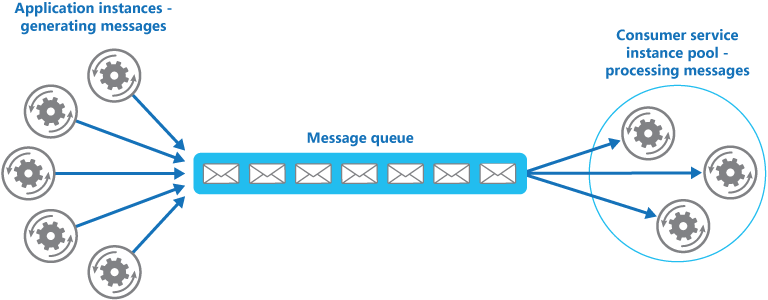
This solution has the following benefits:
- It provides a load-leveled system that can handle wide variations in the volume of requests sent by application instances. The queue acts as a buffer between the application instances and the consumer service instances. This can help to minimize the impact on availability and responsiveness for both the application and the service instances, as described by the Queuebased Load Leveling pattern. Handling a message that requires some long-running processing doesn't prevent other messages from being handled concurrently by other instances of the consumer service.
- It improves reliability. If a producer communicates directly with a consumer instead of using this pattern, but doesn't monitor the consumer, there's a high probability that messages could be lost or fail to be processed if the consumer fails. In this pattern, messages aren't sent to a specific service instance. A failed service instance won't block a producer, and messages can be processed by any working service instance.
- It doesn't require complex coordination between the consumers, or between the producer and the consumer instances. The message queue ensures that each message is delivered at least once.
- It's scalable. The system can dynamically increase or decrease the number of instances of the consumer service as the volume of messages fluctuates.
- It can improve resiliency if the message queue provides transactional read operations. If a consumer service instance reads and processes the message as part of a transactional operation, and the consumer service instance fails, this pattern can ensure that the message will be returned to the queue to be picked up and handled by another instance of the consumer service.
Issues and considerations
Consider the following points when deciding how to implement this pattern:
Message ordering. The order in which consumer service instances receive messages isn't guaranteed and doesn't necessarily reflect the order in which the messages were created. Design the system to ensure that message processing is idempotent because this will help to eliminate any dependency on the order in which messages are handled. For more information, see Idempotency Patterns on Jonathon Oliver's blog.
Microsoft Azure Service Bus Queues can implement guaranteed first-in-first-out ordering of messages by using message sessions. For more information, see Messaging Patterns Using Sessions.
Designing services for resiliency. If the system is designed to detect and restart failed service instances, it might be necessary to implement the processing performed by the service instances as idempotent operations to minimize the effects of a single message being retrieved and processed more than once.
Detecting poison messages. A malformed message, or a task that requires access to resources that aren't available, can cause a service instance to fail. The system should prevent such messages being returned to the queue, and instead capture and store the details of these messages elsewhere so that they can be analyzed if necessary.
Handling results. The service instance handling a message is fully decoupled from the application logic that generates the message, and they might not be able to communicate directly. If the service instance generates results that must be passed back to the application logic, this information must be stored in a location that's accessible to both. In order to prevent the application logic from retrieving incomplete data the system must indicate when processing is complete.
If you're using Azure, a worker process can pass results back to the application logic by using a dedicated message reply queue. The application logic must be able to correlate these results with the original message. This scenario is described in more detail in the Asynchronous Messaging Primer.
Scaling the messaging system. In a large-scale solution, a single message queue could be overwhelmed by the number of messages and become a bottleneck in the system. In this situation, consider partitioning the messaging system to send messages from specific producers to a particular queue, or use load balancing to distribute messages across multiple message queues.
Ensuring reliability of the messaging system. A reliable messaging system is needed to guarantee that after the application enqueues a message it won't be lost. This is essential for ensuring that all messages are delivered at least once.
When to use this pattern
Use this pattern when:
- The workload for an application is divided into tasks that can run asynchronously.
- Tasks are independent and can run in parallel.
- The volume of work is highly variable, requiring a scalable solution.
- The solution must provide high availability and must be resilient if the processing for a task fails.
This pattern might not be useful when:
- It's not easy to separate the application workload into discrete tasks, or there's a high degree of dependence between tasks. • Tasks must be performed synchronously, and the application logic must wait for a task to complete before continuing.
- Tasks must be performed in a specific sequence.
Some messaging systems support sessions that enable a producer to group messages together and ensure that they're all handled by the same consumer. This mechanism can be used with prioritized messages (if they are supported) to implement a form of message ordering that delivers messages in sequence from a producer to a single consumer.
Example
Azure provides storage queues and Service Bus queues that can act as a mechanism for implementing this pattern. The application logic can post messages to a queue, and consumers implemented as tasks in one or more roles can retrieve messages from this queue and process them. For resiliency, a Service Bus queue enables a consumer to use PeekLock mode when it retrieves a message from the queue. This mode doesn't actually remove the message, but simply hides it from other consumers. The original consumer can delete the message when it's finished processing it. If the consumer fails, the peek lock will time out and the message will become visible again allowing another consumer to retrieve it.
For detailed information on using Azure Service Bus queues, see Service Bus queues, topics, and subscriptions. For information on using Azure storage queues, see Get started with Azure Queue storage using .NET.
The following code from the QueueManager class in CompetingConsumers solution available on GitHub shows how you can create a queue by using a QueueClient instance in the Start event handler in a web or worker role.
private string queueName = ...;
private string connectionString = ...;
...
public async Task Start() {
// Check if the queue already exists.
var manager = NamespaceManager.CreateFromConnectionString(this.connectionString);
if (!manager.QueueExists(this.queueName)) {
var queueDescription = new QueueDescription(this.queueName);
// Set the maximum delivery count for messages in the queue. A message
// is automatically dead-lettered after this number of deliveries. The
// default value for dead letter count is 10.
queueDescription.MaxDeliveryCount = 3;
await manager.CreateQueueAsync(queueDescription);
}
...
// Create the queue client. By default the PeekLock method is used.
this.client = QueueClient.CreateFromConnectionString(
this.connectionString, this.queueName);
}
The next code snippet shows how an application can create and send a batch of messages to the queue.
public async Task SendMessagesAsync() {
// Simulate sending a batch of messages to the queue.
var messages = new List < BrokeredMessage > ();
for (int i = 0; i < 10; i++) {
var message = new BrokeredMessage() {
MessageId = Guid.NewGuid().ToString()
};
messages.Add(message);
}
await this.client.SendBatchAsync(messages);
}
The following code shows how a consumer service instance can receive messages from the queue by following an event-driven approach. The processMessageTask parameter to the ReceiveMessages method is a delegate that references the code to run when a message is received. This code is run asynchronously.
private ManualResetEvent pauseProcessingEvent;
...
public void ReceiveMessages(Func < BrokeredMessage, Task > processMessageTask) {
// Set up the options for the message pump.
var options = new OnMessageOptions();
// When AutoComplete is disabled it's necessary to manually
// complete or abandon the messages and handle any errors.
options.AutoComplete = false;
options.MaxConcurrentCalls = 10;
options.ExceptionReceived += this.OptionsOnExceptionReceived;
// Use of the Service Bus OnMessage message pump.
// The OnMessage method must be called once, otherwise an exception will occur.
this.client.OnMessageAsync(
async(msg) => {
// Will block the current thread if Stop is called.
this.pauseProcessingEvent.WaitOne();
// Execute processing task here.
await processMessageTask(msg);
},
options);
}
...
private void OptionsOnExceptionReceived(object sender,
ExceptionReceivedEventArgs exceptionReceivedEventArgs) {
...
}
Note that autoscaling features, such as those available in Azure, can be used to start and stop role instances as the queue length fluctuates. For more information, see Autoscaling Guidance. Also, it's not necessary to maintain a one-to-one correspondence between role instances and worker processes—a single role instance can implement multiple worker processes. For more information, see Compute Resource Consolidation pattern.
Related patterns and guidance
The following patterns and guidance might be relevant when implementing this pattern:
- Asynchronous Messaging Primer. Message queues are an asynchronous communications mechanism. If a consumer service needs to send a reply to an application, it might be necessary to implement some form of response messaging. The Asynchronous Messaging Primer provides information on how to implement request/reply messaging using message queues.
- Autoscaling Guidance. It might be possible to start and stop instances of a consumer service since the length of the queue applications post messages on varies. Autoscaling can help to maintain throughput during times of peak processing.
- Compute Resource Consolidation Pattern. It might be possible to consolidate multiple instances of a consumer service into a single process to reduce costs and management overhead. The Compute Resource Consolidation pattern describes the benefits and tradeoffs of following this approach.
- Queue-based Load Leveling Pattern. Introducing a message queue can add resiliency to the system, enabling service instances to handle widely varying volumes of requests from application instances. The message queue acts as a buffer, which levels the load. The Queue-based Load Leveling pattern describes this scenario in more detail.
This pattern has a sample application associated with it.
Compute Resource Consolidation pattern
Consolidate multiple tasks or operations into a single computational unit. This can increase compute resource utilization and reduce the costs and management overhead associated with performing compute processing in cloud-hosted applications.
Context and problem
A cloud application often implements a variety of operations. In some solutions it makes sense to follow the design principle of separation of concerns initially and divide these operations into separate computational units that are hosted and deployed individually (for example, as separate App Service web apps, separate Virtual Machines, or separate Cloud Service roles). However, although this strategy can help simplify the logical design of the solution, deploying a large number of computational units as part of the same application can increase runtime hosting costs and make management of the system more complex.

As an example, the figure shows the simplified structure of a cloud-hosted solution that is implemented using more than one computational unit. Each computational unit runs in its own virtual environment. Each function has been implemented as a separate task (labeled Task A through Task E) running in its own computational unit.
Each computational unit consumes chargeable resources, even when it's idle or lightly used. Therefore, this isn't always the most cost-effective solution.
In Azure, this concern applies to roles in a Cloud Service, App Services, and Virtual Machines. These items run in their own virtual environment. Running a collection of separate roles, websites, or virtual machines that are designed to perform a set of well-defined operations, but that need to communicate and cooperate as part of a single solution, can be an inefficient use of resources.
Solution
To help reduce costs, increase utilization, improve communication speed, and reduce management it's possible to consolidate multiple tasks or operations into a single computational unit.
Tasks can be grouped according to criteria based on the features provided by the environment and the costs associated with these features. A common approach is to look for tasks that have a similar profile concerning their scalability, lifetime, and processing requirements. Grouping these together allows them to scale as a unit. The elasticity provided by many cloud environments enables additional instances of a computational unit to be started and stopped according to the workload. For example, Azure provides autoscaling that you can apply to roles in a Cloud Service, App Services, and Virtual Machines. For more information, see Autoscaling Guidance.
As a counter example to show how scalability can be used to determine which operations shouldn't be grouped together, consider the following two tasks:
- Task 1 polls for infrequent, time-insensitive messages sent to a queue.
- Task 2 handles high-volume bursts of network traffic.
The second task requires elasticity that can involve starting and stopping a large number of instances of the computational unit. Applying the same scaling to the first task would simply result in more tasks listening for infrequent messages on the same queue and is a waste of resources.
In many cloud environments it's possible to specify the resources available to a computational unit in terms of the number of CPU cores, memory, disk space, and so on. Generally, the more resources specified, the greater the cost. To save money, it's important to maximize the work an expensive computational unit performs, and not let it become inactive for an extended period.
If there are tasks that require a great deal of CPU power in short bursts, consider consolidating these into a single computational unit that provides the necessary power. However, it's important to balance this need to keep expensive resources busy against the contention that could occur if they are over stressed. For example, long-running, compute-intensive tasks shouldn't share the same computational unit.
Issues and considerations
Consider the following points when implementing this pattern:
Scalability and elasticity. Many cloud solutions implement scalability and elasticity at the level of the computational unit by starting and stopping instances of units. Avoid grouping tasks that have conflicting scalability requirements in the same computational unit.
Lifetime. The cloud infrastructure periodically recycles the virtual environment that hosts a computational unit. When there are many long-running tasks inside a computational unit, it might be necessary to configure the unit to prevent it from being recycled until these tasks have finished. Alternatively, design the tasks by using a check-pointing approach that enables them to stop cleanly, and continue at the point they were interrupted when the computational unit is restarted.
Release cadence. If the implementation or configuration of a task changes frequently, it might be necessary to stop the computational unit hosting the updated code, reconfigure and redeploy the unit, and then restart it. This process will also require that all other tasks within the same computational unit are stopped, redeployed, and restarted.
Security. Tasks in the same computational unit might share the same security context and be able to access the same resources. There must be a high degree of trust between the tasks, and confidence that one task isn't going to corrupt or adversely affect another. Additionally, increasing the number of tasks running in a computational unit increases the attack surface of the unit. Each task is only as secure as the one with the most vulnerabilities.
Fault tolerance. If one task in a computational unit fails or behaves abnormally, it can affect the other tasks running within the same unit. For example, if one task fails to start correctly it can cause the entire startup logic for the computational unit to fail, and prevent other tasks in the same unit from running.
Contention. Avoid introducing contention between tasks that compete for resources in the same computational unit. Ideally, tasks that share the same computational unit should exhibit different resource utilization characteristics. For example, two compute-intensive tasks should probably not reside in the same computational unit, and neither should two tasks that consume large amounts of memory. However, mixing a compute intensive task with a task that requires a large amount of memory is a workable combination.
Complexity. Combining multiple tasks into a single computational unit adds complexity to the code in the unit, possibly making it more difficult to test, debug, and maintain.
Stable logical architecture. Design and implement the code in each task so that it shouldn't need to change, even if the physical environment the task runs in does change.
Other strategies. Consolidating compute resources is only one way to help reduce costs associated with running multiple tasks concurrently. It requires careful planning and monitoring to ensure that it remains an effective approach. Other strategies might be more appropriate, depending on the nature of the work and where the users these tasks are running are located. For example, functional decomposition of the workload (as described by the Compute Partitioning Guidance) might be a better option.
Issues and considerations
Use this pattern for tasks that are not cost effective if they run in their own computational units. If a task spends much of its time idle, running this task in a dedicated unit can be expensive.
This pattern might not be suitable for tasks that perform critical fault-tolerant operations, or tasks that process highly sensitive or private data and require their own security context. These tasks should run in their own isolated environment, in a separate computational unit.
Example
When building a cloud service on Azure, it's possible to consolidate the processing performed by multiple tasks into a single role. Typically this is a worker role that performs background or asynchronous processing tasks.
In some cases it's possible to include background or asynchronous processing tasks in the web role. This technique helps to reduce costs and simplify deployment, although it can impact the scalability and responsiveness of the public-facing interface provided by the web role. The article Combining Multiple Azure Worker Roles into an Azure Web Role contains a detailed description of implementing background or asynchronous processing tasks in a web role.
The role is responsible for starting and stopping the tasks. When the Azure fabric controller loads a role, it raises the Start event for the role. You can override the OnStart method of the WebRole or WorkerRole class to handle this event, perhaps to initialize the data and other resources the tasks in this method depend on.
When the OnStartmethod completes, the role can start responding to requests. You can find more information and guidance about using the OnStart and Run methods in a role in the Application Startup Processes section in the patterns & practices guide Moving Applications to the Cloud.
Keep the code in the OnStart method as concise as possible. Azure doesn't impose any limit on the time taken for this method to complete, but the role won't be able to start responding to network requests sent to it until this method completes.
When the OnStart method has finished, the role executes the Run method. At this point, the fabric controller can start sending requests to the role.
Place the code that actually creates the tasks in the Run method. Note that the Run method defines the lifetime of the role instance. When this method completes, the fabric controller will arrange for the role to be shut down.
When a role shuts down or is recycled, the fabric controller prevents any more incoming requests being received from the load balancer and raises the Stop event. You can capture this event by overriding the OnStop method of the role and perform any tidying up required before the role terminates.
Any actions performed in the OnStop method must be completed within five minutes (or 30 seconds if you are using the Azure emulator on a local computer). Otherwise the Azure fabric controller assumes that the role has stalled and will force it to stop.
The tasks are started by the Run method that waits for the tasks to complete. The tasks implement the business logic of the cloud service, and can respond to messages posted to the role through the Azure load balancer. The figure shows the lifecycle of tasks and resources in a role in an Azure cloud service.

The WorkerRole.cs file in the ComputeResourceConsolidation.Worker project shows an example of how you might implement this pattern in an Azure cloud service.
The ComputeResourceConsolidation.Worker project is part of the ComputeResourceConsolidation solution available for download from GitHub.
The MyWorkerTask1 and the MyWorkerTask2 methods illustrate how to perform different tasks within the same worker role. The following code shows MyWorkerTask1. This is a simple task that sleeps for 30 seconds and then outputs a trace message. It repeats this process until the task is canceled. The code in MyWorkerTask2 is similar.
// A sample worker role task.
private static async Task MyWorkerTask1(CancellationToken ct) {
// Fixed interval to wake up and check for work and/or do work.
var interval = TimeSpan.FromSeconds(30);
try {
while (!ct.IsCancellationRequested) {
// Wake up and do some background processing if not canceled.
// TASK PROCESSING CODE HERE
Trace.TraceInformation("Doing Worker Task 1 Work");
// Go back to sleep for a period of time unless asked to cancel.
// Task.Delay will throw an OperationCanceledException when canceled.
await Task.Delay(interval, ct);
}
} catch (OperationCanceledException) {
// Expect this exception to be thrown in normal circumstances or check
// the cancellation token. If the role instances are shutting down, a
// cancellation request will be signaled.
Trace.TraceInformation("Stopping service, cancellation requested");
// Rethrow the exception.
throw;
}
}
The sample code shows a common implementation of a background process. In a real world application you can follow this same structure, except that you should place your own processing logic in the body of the loop that waits for the cancellation request.
After the worker role has initialized the resources it uses, the Run method starts the two tasks concurrently, as shown here.
/// <summary>
/// The cancellation token source use to cooperatively cancel running tasks
/// </summary>
private readonly CancellationTokenSource cts = new CancellationTokenSource();
/// <summary>
/// List of running tasks on the role instance
/// </summary>
private readonly List < Task > tasks = new List < Task > ();
// RoleEntry Run() is called after OnStart().
// Returning from Run() will cause a role instance to recycle.
public override void Run() {
// Start worker tasks and add to the task list
tasks.Add(MyWorkerTask1(cts.Token));
tasks.Add(MyWorkerTask2(cts.Token));
foreach(var worker in this.workerTasks) {
this.tasks.Add(worker);
}
Trace.TraceInformation("Worker host tasks started");
// The assumption is that all tasks should remain running and not return,
// similar to role entry Run() behavior.
try {
Task.WaitAll(tasks.ToArray());
} catch (AggregateException ex) {
Trace.TraceError(ex.Message);
// If any of the inner exceptions in the aggregate exception
// are not cancellation exceptions then re-throw the exception.
ex.Handle(innerEx => (innerEx is OperationCanceledException));
}
// If there wasn't a cancellation request, stop all tasks and return from Run()
// An alternative to canceling and returning when a task exits would be to
// restart the task.
if (!cts.IsCancellationRequested) {
Trace.TraceInformation("Task returned without cancellation request");
Stop(TimeSpan.FromMinutes(5));
}
}
...
In this example, the Run method waits for tasks to be completed. If a task is canceled, the Run method assumes that the role is being shut down and waits for the remaining tasks to be canceled before finishing (it waits for a maximum of five minutes before terminating). If a task fails due to an expected exception, the Run method cancels the task.
You could implement more comprehensive monitoring and exception handling strategies in the Run method such as restarting tasks that have failed, or including code that enables the role to stop and start individual tasks.
The Stop method shown in the following code is called when the fabric controller shuts down the role instance (it's invoked from the OnStop method). The code stops each task gracefully by canceling it. If any task takes more than five minutes to complete, the cancellation processing in the Stop method ceases waiting and the role is terminated.
// Stop running tasks and wait for tasks to complete before returning
// unless the timeout expires.
private void Stop(TimeSpan timeout) {
Trace.TraceInformation("Stop called.Canceling tasks.");
// Cancel running tasks.
cts.Cancel();
Trace.TraceInformation("Waiting
for canceled tasks to finish and
return");
// Wait for all the tasks to complete before returning. Note that the
// emulator currently allows 30 seconds and Azure allows five
// minutes for processing to complete.
try {
Task.WaitAll(tasks.ToArray(), timeout);
} catch (AggregateException ex) {
Trace.TraceError(ex.Message);
// If any of the inner exceptions in the aggregate exception
// are not cancellation exceptions then rethrow the exception.
ex.Handle(innerEx => (innerEx is OperationCanceledException));
}
}
Related patterns and guidance
The following patterns and guidance might also be relevant when implementing this pattern:
- Autoscaling Guidance. Autoscaling can be used to start and stop instances of service hosting computational resources, depending on the anticipated demand for processing.
- Compute Partitioning Guidance. Describes how to allocate the services and components in a cloud service in a way that helps to minimize running costs while maintaining the scalability, performance, availability, and security of the service.
- This pattern includes a downloadable sample application.
Event Sourcing pattern
Instead of storing just the current state of the data in a domain, use an append-only store to record the full series of actions taken on that data. The store acts as the system of record and can be used to materialize the domain objects. This can simplify tasks in complex domains, by avoiding the need to synchronize the data model and the business domain, while improving performance, scalability, and responsiveness. It can also provide consistency for transactional data, and maintain full audit trails and history that can enable compensating actions.
Context and problem
Most applications work with data. The typical approach is for the application to maintain the current state of the data by updating it as users work with it. For example, in the traditional create, read, update, and delete (CRUD) model a typical data process is to read data from the store, make some modifications to it, and update the current state of the data with the new values—often by using transactions that lock the data.
The CRUD approach has some limitations:
- CRUD systems perform update operations directly against a data store, which can slow down performance and responsiveness, and limit scalability, due to the processing overhead it requires.
- In a collaborative domain with many concurrent users, data update conflicts are more likely because the update operations take place on a single item of data.
- Unless there's an additional auditing mechanism that records the details of each operation in a separate log, history is lost.
For a deeper understanding of the limits of the CRUD approach see CRUD, Only When You Can Afford It.
Solution
The Event Sourcing pattern defines an approach to handling operations on data that's driven by a sequence of events, each of which is recorded in an append-only store. Application code sends a series of events that imperatively describe each action that has occurred on the data to the event store where they're persisted. Each event represents a set of changes to the data (such as AddedItemToOrder).
The events are persisted in an event store that acts as the system of record (the authoritative data source) about the current state of the data. The event store typically publishes these events so that consumers can be notified and can handle them if needed. Consumers could, for example, initiate tasks that apply the operations in the events to other systems, or perform any other associated action that's required to complete the operation. Notice that the application code that generates the events is decoupled from the systems that subscribe to the events.
Typical uses of the events published by the event store are to maintain materialized views of entities as actions in the application change them, and for integration with external systems. For example, a system can maintain a materialized view of all customer orders that's used to populate parts of the UI. As the application adds new orders, adds or removes items on the order, and adds shipping information, the events that describe these changes can be handled and used to update the materialized view.
In addition, at any point it's possible for applications to read the history of events, and use it to materialize the current state of an entity by playing back and consuming all the events related to that entity. This can occur on demand to materialize a domain object when handling a request, or through a scheduled task so that the state of the entity can be stored as a materialized view to support the presentation layer.
The figure shows an overview of the pattern, including some of the options for using the event stream such as creating a materialized view, integrating events with external applications and systems, and replaying events to create projections of the current state of specific entities.

The Event Sourcing pattern provides the following advantages:
Events are immutable and can be stored using an append-only operation. The user interface, workflow, or process that initiated an event can continue, and tasks that handle the events can run in the background. This combined with the fact that there's no contention during the processing of transactions can vastly improve performance and scalability for applications, especially for the presentation level or user interface.
Events are simple objects that describe some action that occurred together with any associated data required to describe the action represented by the event. Events don't directly update a data store. They're simply recorded for handling at the appropriate time. This can simplify implementation and management.
Events typically have meaning for a domain expert, whereas object-relational impedance mismatch can make complex database tables hard to understand. Tables are artificial constructs that represent the current state of the system, not the events that occurred.
Event sourcing can help prevent concurrent updates from causing conflicts because it avoids the requirement to directly update objects in the data store. However, the domain model must still be designed to protect itself from requests that might result in an inconsistent state.
The append-only storage of events provides an audit trail that can be used to monitor actions taken against a data store, regenerate the current state as materialized views or projections by replaying the events at any time, and assist in testing and debugging the system. In addition, the requirement to use compensating events to cancel changes provides a history of changes that were reversed, which wouldn't be the case if the model simply stored the current state. The list of events can also be used to analyze application performance and detect user behavior trends or to obtain other useful business information.
The event store raises events, and tasks perform operations in response to those events. This decoupling of the tasks from the events provides flexibility and extensibility. Tasks know about the type of event and the event data, but not about the operation that triggered the event. In addition, multiple tasks can handle each event. This enables easy integration with other services and systems that only listen for new events raised by the event store. However, the event sourcing events tend to be very low level, and it might be necessary to generate specific integration events instead.
Event sourcing is commonly combined with the CQRS pattern by performing the data management tasks in response to the events, and by materializing views from the stored events.
Issues and considerations
Consider the following points when deciding how to implement this pattern:
The system will only be eventually consistent when creating materialized views or generating projections of data by replaying events. There's some delay between an application adding events to the event store as the result of handling a request, the events being published, and consumers of the events handling them. During this period, new events that describe further changes to entities might have arrived at the event store.
Notes: See the Data Consistency Primer for information about eventual consistency.
The event store is the permanent source of informatio, and so the event data should never be updated. The only way to update an entity to undo a change is to add a compensating event to the event store. If the format (rather than the data) of the persisted events needs to change, perhaps during a migration, it can be difficult to combine existing events in the store with the new version. It might be necessary to iterate through all the events making changes so they're compliant with the new format, or add new events that use the new format. Consider using a version stamp on each version of the event schema to maintain both the old and the new event formats.
Multi-threaded applications and multiple instances of applications might be storing events in the event store. The consistency of events in the event store is vital, as is the order of events that affect a specific entity (the order that changes occur to an entity affects its current state). Adding a timestamp to every event can help to avoid issues. Another common practice is to annotate each event resulting from a request with an incremental identifier. If two actions attempt to add events for the same entity at the same time, the event store can reject an event that matches an existing entity identifier and event identifier.
There's no standard approach, or existing mechanisms such as SQL queries, for reading the events to obtain information. The only data that can be extracted is a stream of events using an event identifier as the criteria. The event ID typically maps to individual entities. The current state of an entity can be determined only by replaying all of the events that relate to it against the original state of that entity.
The length of each event stream affects managing and updating the system. If the streams are large, consider creating snapshots at specific intervals such as a specified number of events. The current state of the entity can be obtained from the snapshot and by replaying any events that occurred after that point in time. For more information about creating snapshots of data, see Snapshot on Martin Fowler's Enterprise Application Architecture website and Master-Subordinate Snapshot Replication.
Even though event sourcing minimizes the chance of conflicting updates to the data, the application must still be able to deal with inconsistencies that result from eventual consistency and the lack of transactions. For example, an event that indicates a reduction in stock inventory might arrive in the data store while an order for that item is being placed, resulting in a requirement to reconcile the two operations either by advising the customer or creating a back order.
Event publication might be "at least once," and so consumers of the events must be idempotent. They must not reapply the update described in an event if the event is handled more than once. For example, if multiple instances of a consumer maintain an aggregate an entity's property, such as the total number of orders placed, only one must succeed in incrementing the aggregate when an order placed event occurs. While this isn't a key characteristic of event sourcing, it's the usual implementation decision.
When to use this pattern
Use this pattern in the following scenarios:
- When you want to capture intent, purpose, or reason in the data. For example, changes to a customer entity can be captured as a series of specific event types such as Moved home, Closed account, or Deceased.
- When it's vital to minimize or completely avoid the occurrence of conflicting updates to data.
- When you want to record events that occur, and be able to replay them to restore the state of a system, roll back changes, or keep a history and audit log. For example, when a task involves multiple steps you might need to execute actions to revert updates and then replay some steps to bring the data back into a consistent state.
- When using events is a natural feature of the operation of the application, and requires little additional development or implementation effort.
- When you need to decouple the process of inputting or updating data from the tasks required to apply these actions. This might be to improve UI performance, or to distribute events to other listeners that take action when the events occur. For example, integrating a payroll system with an expense submission website so that events raised by the event store in response to data updates made in the website are consumed by both the website and the payroll system.
- When you want flexibility to be able to change the format of materialized models and entity data if requirements change, or—when used in conjunction with CQRS—you need to adapt a read model or the views that expose the data.
- When used in conjunction with CQRS, and eventual consistency is acceptable while a read model is updated, or the performance impact of rehydrating entities and data from an event stream is acceptable.
This pattern might not be useful in the following situations:
- Small or simple domains, systems that have little or no business logic, or nondomain systems that naturally work well with traditional CRUD data management mechanisms.
- Systems where consistency and real-time updates to the views of the data are required.
- Systems where audit trails, history, and capabilities to roll back and replay actions are not required.
- Systems where there's only a very low occurrence of conflicting updates to the underlying data. For example, systems that predominantly add data rather than updating it.
Example
A conference management system needs to track the number of completed bookings for a conference so that it can check whether there are seats still available when a potential attendee tries to make a booking. The system could store the total number of bookings for a conference in at least two ways:
- The system could store the information about the total number of bookings as a separate entity in a database that holds booking information. As bookings are made or canceled, the system could increment or decrement this number as appropriate. This approach is simple in theory, but can cause scalability issues if a large number of attendees are attempting to book seats during a short period of time. For example, in the last day or so prior to the booking period closing.
- The system could store information about bookings and cancellations as events held in an event store. It could then calculate the number of seats available by replaying these events. This approach can be more scalable due to the immutability of events. The system only needs to be able to read data from the event store, or append data to the event store. Event information about bookings and cancellations is never modified.
The following diagram illustrates how the seat reservation subsystem of the conference management system might be implemented using event sourcing.

The sequence of actions for reserving two seats is as follows:
- The user interface issues a command to reserve seats for two attendees. The command is handled by a separate command handler. A piece of logic that is decoupled from the user interface and is responsible for handling requests posted as commands.
- An aggregate containing information about all reservations for the conference is constructed by querying the events that describe bookings and cancellations. This aggregate is called SeatAvailability, and is contained within a domain model that exposes methods for querying and modifying the data in the aggregate.
- Some optimizations to consider are using snapshots (so that you don't need to query and replay the full list of events to obtain the current state of the aggregate), and maintaining a cached copy of the aggregate in memory.
- The command handler invokes a method exposed by the domain model to make the reservations.
- The SeatAvailability aggregate records an event containing the number of seats that were reserved. The next time the aggregate applies events, all the reservations will be used to compute how many seats remain.
- The system appends the new event to the list of events in the event store.
If a user cancels a seat, the system follows a similar process except the command handler issues a command that generates a seat cancellation event and appends it to the event store.
As well as providing more scope for scalability, using an event store also provides a complete history, or audit trail, of the bookings and cancellations for a conference. The events in the event store are the accurate record. There is no need to persist aggregates in any other way because the system can easily replay the events and restore the state to any point in time.
You can find more information about this example in Introducing Event Sourcing.
Related patterns and guidance
The following patterns and guidance might also be relevant when implementing this pattern:
- Command and Query Responsibility Segregation (CQRS) Pattern. The write store that provides the permanent source of information for a CQRS implementation is often based on an implementation of the Event Sourcing pattern. Describes how to segregate the operations that read data in an application from the operations that update data by using separate interfaces.
- Materialized View Pattern. The data store used in a system based on event sourcing is typically not well suited to efficient querying. Instead, a common approach is to generate prepopulated views of the data at regular intervals, or when the data changes. Shows how this can be done.
- Compensating Transaction Pattern. The existing data in an event sourcing store is not updated, instead new entries are added that transition the state of entities to the new values. To reverse a change, compensating entries are used because it isn't possible to simply reverse the previous change. Describes how to undo the work that was performed by a previous operation.
- Data Consistency Primer. When using event sourcing with a separate read store or materialized views, the read data won't be immediately consistent, instead it'll be only eventually consistent. Summarizes the issues surrounding maintaining consistency over distributed data.
- Data Partitioning Guidance. Data is often partitioned when using event sourcing to improve scalability, reduce contention, and optimize performance. Describes how to divide data into discrete partitions, and the issues that can arise.
- Greg Young's post Why use Event Sourcing?
External Configuration Store pattern
Move configuration information out of the application deployment package to a centralized location. This can provide opportunities for easier management and control of configuration data, and for sharing configuration data across applications and application instances.
Context and problem
The majority of application runtime environments include configuration information that's held in files deployed with the application. In some cases, it's possible to edit these files to change the application behavior after it's been deployed. However, changes to the configuration require the application be redeployed, often resulting in unacceptable downtime and other administrative overhead.
Local configuration files also limit the configuration to a single application, but sometimes it would be useful to share configuration settings across multiple applications. Examples include database connection strings, UI theme information, or the URLs of queues and storage used by a related set of applications.
It's challenging to manage changes to local configurations across multiple running instances of the application, especially in a cloud-hosted scenario. It can result in instances using different configuration settings while the update is being deployed.
In addition, updates to applications and components might require changes to configuration schemas. Many configuration systems don't support different versions of configuration information.
Solution
Store the configuration information in external storage, and provide an interface that can be used to quickly and efficiently read and update configuration settings. The type of external store depends on the hosting and runtime environment of the application. In a cloud-hosted scenario it's typically a cloud-based storage service, but could be a hosted database or other system.
The backing store you choose for configuration information should have an interface that provides consistent and easy-to-use access. It should expose the information in a correctly typed and structured format. The implementation might also need to authorize users access in order to protect configuration data, and be flexible enough to allow storage of multiple versions of the configuration (such as development, staging, or production, including multiple release versions of each one).
Many built-in configuration systems read the data when the application starts up, and cache the data in memory to provide fast access and minimize the impact on application performance. Depending on the type of backing store used, and the latency of this store, it might be helpful to implement a caching mechanism within the external configuration store. For more information, see the Caching Guidance. The figure illustrates an overview of the External Configuration Store pattern with optional local cache.

Issues and considerations
Consider the following points when deciding how to implement this pattern:
Choose a backing store that offers acceptable performance, high availability, robustness, and can be backed up as part of the application maintenance and administration process. In a cloud-hosted application, using a cloud storage mechanism is usually a good choice to meet these requirements.
Design the schema of the backing store to allow flexibility in the types of information it can hold. Ensure that it provides for all configuration requirements such as typed data, collections of settings, multiple versions of settings, and any other features that the applications using it require. The schema should be easy to extend to support additional settings as requirements change.
Consider the physical capabilities of the backing store, how it relates to the way configuration information is stored, and the effects on performance. For example, storing an XML document containing configuration information will require either the configuration interface or the application to parse the document in order to read individual settings. It'll make updating a setting more complicated, though caching the settings can help to offset slower read performance.
Consider how the configuration interface will permit control of the scope and inheritance of configuration settings. For example, it might be a requirement to scope configuration settings at the organization, application, and the machine level. It might need to support delegation of control over access to different scopes, and to prevent or allow individual applications to override settings.
Ensure that the configuration interface can expose the configuration data in the required formats such as typed values, collections, key/value pairs, or property bags.
Consider how the configuration store interface will behave when settings contain errors, or don't exist in the backing store. It might be appropriate to return default settings and log errors. Also consider aspects such as the case sensitivity of configuration setting keys or names, the storage and handling of binary data, and the ways that null or empty values are handled.
Consider how to protect the configuration data to allow access to only the appropriate users and applications. This is likely a feature of the configuration store interface, but it's also necessary to ensure that the data in the backing store can't be accessed directly without the appropriate permission. Ensure strict separation between the permissions required to read and to write configuration data. Also consider whether you need to encrypt some or all of the configuration settings, and how this'll be implemented in the configuration store interface.
Centrally stored configurations, which change application behavior during runtime, are critically important and should be deployed, updated, and managed using the same mechanisms as deploying application code. For example, changes that can affect more than one application must be carried out using a full test and staged deployment approach to ensure that the change is appropriate for all applications that use this configuration. If an administrator edits a setting to update one application, it could adversely impact other applications that use the same setting.
If an application caches configuration information, the application needs to be alerted if the configuration changes. It might be possible to implement an expiration policy over cached configuration data so that this information is automatically refreshed periodically and any changes picked up (and acted on).
When to use this pattern
This pattern is useful for:
- Configuration settings that are shared between multiple applications and application instances, or where a standard configuration must be enforced across multiple applications and application instances.
- A standard configuration system that doesn't support all of the required configuration settings, such as storing images or complex data types.
- As a complementary store for some of the settings for applications, perhaps allowing applications to override some or all of the centrally-stored settings.
- As a way to simplify administration of multiple applications, and optionally for monitoring use of configuration settings by logging some or all types of access to the configuration store.
Example
In a Microsoft Azure hosted application, a typical choice for storing configuration information externally is to use Azure Storage. This is resilient, offers high performance, and is replicated three times with automatic failover to offer high availability. Azure Table storage provides a key/value store with the ability to use a flexible schema for the values. Azure Blob storage provides a hierarchical, container-based store that can hold any type of data in individually named blobs.
The following example shows how a configuration store can be implemented over Blob storage to store and expose configuration information. The BlobSettingsStore class abstracts Blob storage for holding configuration information, and implements the ISettingsStore interface shown in the following code.
public interface ISettingsStore {
Task<string> GetVersionAsync();
Task<Dictionary<string, string>> FindAllAsync();
}
This interface defines methods for retrieving and updating configuration settings held in the configuration store, and includes a version number that can be used to detect whether any configuration settings have been modified recently. The BlobSettingsStore class uses the ETag property of the blob to implement versioning. The ETag property is updated automatically each time the blob is written.
By design, this simple solution exposes all configuration settings as string values rather than typed values.
The ExternalConfigurationManager class provides a wrapper around a BlobSettingsStore object.
An application can use this class to store and retrieve configuration information. This class uses the Microsoft Reactive Extensions library to expose any changes made to the configuration through an implementation of the IObservable interface. If a setting is modified by calling the SetAppSetting method, the Changed event is raised and all subscribers to this event will be notified.
Note that all settings are also cached in a Dictionary object inside the ExternalConfigurationManager class for fast access. The GetSetting method used to retrieve a configuration setting reads the data from the cache. If the setting isn't found in the cache, it's retrieved from the BlobSettingsStore object instead.
The GetSettings method invokes the CheckForConfigurationChanges method to detect whether the configuration information in blob storage has changed. It does this by examining the version number and comparing it with the current version number held by the ExternalConfigurationManager object. If one or more changes have occurred, the Changed event is raised and the configuration settings cached in the Dictionary object are refreshed. This is an application of the Cache-Aside pattern.
The following code sample shows how the Changed event, the GetSettings method, and the CheckForConfigurationChanges method are implemented:
public class ExternalConfigurationManager: IDisposable {
// An abstraction of the configuration store.
private readonly ISettingsStore settings;
private readonly ISubject < KeyValuePair < string, string >> changed;
...
private readonly ReaderWriterLockSlim settingsCacheLock = new ReaderWriterLockSlim();
private readonly SemaphoreSlim syncCacheSemaphore = new SemaphoreSlim(1);
...
private Dictionary < string, string > settingsCache;
private string currentVersion;
...
public ExternalConfigurationManager(ISettingsStore settings, ...) {
this.settings = settings;
...
}
...
public IObservable < KeyValuePair < string, string >> Changed => this.changed.AsObservable();
...
public string GetAppSetting(string key) {
...
// Try to get the value from the settings cache.
// If there's a cache miss, get the setting from the settings store and refresh the settings
cache.
string value;
try {
this.settingsCacheLock.EnterReadLock();
this.settingsCache.TryGetValue(key, out value);
} finally {
this.settingsCacheLock.ExitReadLock();
}
return value;
}
...
private void CheckForConfigurationChanges() {
try {
// It is assumed that updates are infrequent.
// To avoid race conditions in refreshing the cache, synchronize access to the in-memory
cache.
await this.syncCacheSemaphore.WaitAsync();
var latestVersion = await this.settings.GetVersionAsync();
// If the versions are the same, nothing has changed in the configuration.
if (this.currentVersion == latestVersion) return;
// Get the latest settings from the settings store and publish changes.
var latestSettings = await this.settings.FindAllAsync();
// Refresh the settings cache.
try {
this.settingsCacheLock.EnterWriteLock();
if (this.settingsCache != null) {
//Notify settings changed
latestSettings.Except(this.settingsCache).ToList().ForEach(kv => this.changed.OnNext(kv));
}
this.settingsCache = latestSettings;
} finally {
this.settingsCacheLock.ExitWriteLock();
}
// Update the current version.
this.currentVersion = latestVersion;
} catch (Exception ex) {
this.changed.OnError(ex);
} finally {
this.syncCacheSemaphore.Release();
}
}
}
The ExternalConfigurationManager class also provides a property named Environment. This property supports varying configurations for an application running in different environments, such as staging and production.
An ExternalConfigurationManager object can also query the BlobSettingsStore object periodically for any changes. In the following code, the StartMonitor method calls CheckForConfigurationChanges at an interval to detect any changes and raise the Changed event, as described earlier.
public class ExternalConfigurationManager: IDisposable {
...
private readonly ISubject < KeyValuePair < string,
string >> changed;
private Dictionary < string,
string > settingsCache;
private readonly CancellationTokenSource cts = new CancellationTokenSource();
private Task monitoringTask;
private readonly TimeSpan interval;
private readonly SemaphoreSlim timerSemaphore = new SemaphoreSlim(1);
...
public ExternalConfigurationManager(string environment): this(new BlobSettingsStore(environment), TimeSpan.FromSeconds(15), environment) {}
public ExternalConfigurationManager(ISettingsStore settings, TimeSpan interval, string environment) {
this.settings = settings;
this.interval = interval;
this.CheckForConfigurationChangesAsync().Wait();
this.changed = new Subject < KeyValuePair < string, string >> ();
this.Environment = environment;
}
...
/// <summary>
/// Check to see if the current instance is monitoring for changes
/// </summary>
public bool IsMonitoring => this.monitoringTask != null && !this.monitoringTask.IsCompleted;
/// <summary>
/// Start the background monitoring for configuration changes in the central store
/// </summary>
public void StartMonitor() {
if (this.IsMonitoring)
return;
try {
this.timerSemaphore.Wait();
// Check again to make sure we are not already running.
if (this.IsMonitoring)
return;
// Start running our task loop.
this.monitoringTask = ConfigChangeMonitor();
} finally {
this.timerSemaphore.Release();
}
}
/// <summary>
/// Loop that monitors for configuration changes
/// </summary>
/// <returns></returns>
public async Task ConfigChangeMonitor() {
while (!cts.Token.IsCancellationRequested) {
await this.CheckForConfigurationChangesAsync();
await Task.Delay(this.interval, cts.Token);
}
}
/// <summary>
/// Stop monitoring for configuration changes
/// </summary>
public void StopMonitor() {
try {
this.timerSemaphore.Wait();
// Signal the task to stop.
this.cts.Cancel();
// Wait for the loop to stop.
this.monitoringTask.Wait();
this.monitoringTask = null;
} finally {
this.timerSemaphore.Release();
}
}
public void Dispose() {
this.cts.Cancel();
}
...
}
The ExternalConfigurationManager class is instantiated as a singleton instance by the ExternalConfiguration class shown below.
public static class ExternalConfiguration {
private static readonly Lazy < ExternalConfigurationManager > configuredInstance = new
Lazy < ExternalConfigurationManager > (
() => {
var environment = CloudConfigurationManager.GetSetting("environment");
return new ExternalConfigurationManager(environment);
});
public static ExternalConfigurationManager Instance => configuredInstance.Value;
}
The following code is taken from the WorkerRole class in the ExternalConfigurationStore.Cloud project. It shows how the application uses the ExternalConfiguration class to read a setting.
public override void Run() {
// Start monitoring configuration changes.
ExternalConfiguration.Instance.StartMonitor();
// Get a setting.
var setting = ExternalConfiguration.Instance.GetAppSetting("setting1");
Trace.TraceInformation("Worker Role: Get setting1, value: "+setting);
this.completeEvent.WaitOne();
}
The following code, also from the WorkerRole class, shows how the application subscribes to configuration events.
public override bool OnStart() {
...
// Subscribe to the event.
ExternalConfiguration.Instance.Changed.Subscribe(
m => Trace.TraceInformation("Configuration has changed.Key: {
0
}
Value: {
1
}",
m.Key, m.Value),
ex => Trace.TraceError("Error detected: "+ex.Message));
...
}
Related patterns and guidance
- A sample that demonstrates this pattern is available on GitHub.
Federated Identity pattern
Delegate authentication to an external identity provider. This can simplify development, minimize the requirement for user administration, and improve the user experience of the application.
Context and problem
Users typically need to work with multiple applications provided and hosted by different organizations they have a business relationship with. These users might be required to use specific (and different) credentials for each one. This can:
- Cause a disjointed user experience. Users often forget sign-in credentials when they have many different ones.
- Expose security vulnerabilities. When a user leaves the company the account must immediately be deprovisioned. It's easy to overlook this in large organizations.
- Complicate user management. Administrators must manage credentials for all of the users, and perform additional tasks such as providing password reminders.
Users typically prefer to use the same credentials for all these applications.
Solution
Implement an authentication mechanism that can use federated identity. Separate user authentication from the application code, and delegate authentication to a trusted identity provider. This can simplify development and allow users to authenticate using a wider range of identity providers (IdP) while minimizing the administrative overhead. It also allows you to clearly decouple authentication from authorization.
The trusted identity providers include corporate directories, on-premises federation services, other security token services (STS) provided by business partners, or social identity providers that can authenticate users who have, for example, a Microsoft, Google, Yahoo!, or Facebook account.
The figure illustrates the Federated Identity pattern when a client application needs to access a service that requires authentication. The authentication is performed by an IdP that works in concert with an STS. The IdP issues security tokens that provide information about the authenticated user. This information, referred to as claims, includes the user's identity, and might also include other information such as role membership and more granular access rights.

This model is often called claims-based access control. Applications and services authorize access to features and functionality based on the claims contained in the token. The service that requires authentication must trust the IdP. The client application contacts the IdP that performs the authentication. If the authentication is successful, the IdP returns a token containing the claims that identify the user to the STS (note that the IdP and STS can be the same service). The STS can transform and augment the claims in the token based on predefined rules, before returning it to the client. The client application can then pass this token to the service as proof of its identity.
There might be additional STSs in the chain of trust. For example, in the scenario described later, an on-premises STS trusts another STS that is responsible for accessing an identity provider to authenticate the user. This approach is common in enterprise scenarios where there's an on-premises STS and directory.
Federated authentication provides a standards-based solution to the issue of trusting identities across diverse domains, and can support single sign-on. It's becoming more common across all types of applications, especially cloud-hosted applications, because it supports single sign-on without requiring a direct network connection to identity providers. The user doesn't have to enter credentials for every application. This increases security because it prevents the creation of credentials required to access many different applications, and it also hides the user's credentials from all but the original identity provider. Applications see just the authenticated identity information contained within the token.
Federated identity also has the major advantage that management of the identity and credentials is the responsibility of the identity provider. The application or service doesn't need to provide identity management features. In addition, in corporate scenarios, the corporate directory doesn't need to know about the user if it trusts the identity provider. This removes all the administrative overhead of managing the user identity within the directory.
Issues and considerations
Consider the following when designing applications that implement federated authentication:
- Authentication can be a single point of failure. If you deploy your application to multiple datacenters, consider deploying your identity management mechanism to the same datacenters to maintain application reliability and availability.
- Authentication tools make it possible to configure access control based on role claims contained in the authentication token. This is often referred to as role-based access control (RBAC), and it can allow a more granular level of control over access to features and resources.
- Unlike a corporate directory, claims-based authentication using social identity providers doesn't usually provide information about the authenticated user other than an email address, and perhaps a name. Some social identity providers, such as a Microsoft account, provide only a unique identifier. The application usually needs to maintain some information on registered users, and be able to match this information to the identifier contained in the claims in the token. Typically this is done through registration when the user first accesses the application, and information is then injected into the token as additional claims after each authentication.
- If there's more than one identity provider configured for the STS, it must detect which identity provider the user should be redirected to for authentication. This process is called home realm discovery. The STS might be able to do this automatically based on an email address or user name that the user provides, a subdomain of the application that the user is accessing, the user's IP address scope, or on the contents of a cookie stored in the user's browser. For example, if the user entered an email address in the Microsoft domain, such as user@live.com, the STS will redirect the user to the Microsoft account sign-in page. On later visits, the STS could use a cookie to indicate that the last sign in was with a Microsoft account. If automatic discovery can't determine the home realm, the STS will display a home realm discovery page that lists the trusted identity providers, and the user must select the one they want to use.
When to use this pattern
This pattern is useful for scenarios such as:
- Single sign-on in the enterprise. In this scenario you need to authenticate employees for corporate applications that are hosted in the cloud outside the corporate security boundary, without requiring them to sign in every time they visit an application. The user experience is the same as when using on-premises applications where they're authenticated when signing in to a corporate network, and from then on have access to all relevant applications without needing to sign in again.
- Federated identity with multiple partners. In this scenario you need to authenticate both corporate employees and business partners who don't have accounts in the corporate directory. This is common in business-to-business applications, applications that integrate with third-party services, and where companies with different IT systems have merged or shared resources.
- Federated identity in SaaS applications. In this scenario independent software vendors provide a ready-to-use service for multiple clients or tenants. Each tenant authenticates using a suitable identity provider. For example, business users will use their corporate credentials, while consumers and clients of the tenant will use their social identity credentials.
This pattern might not be useful in the following situations:
- All users of the application can be authenticated by one identity provider, and there's no requirement to authenticate using any other identity provider. This is typical in business applications that use a corporate directory (accessible within the application) for authentication, by using a VPN, or (in a cloud-hosted scenario) through a virtual network connection between the on-premises directory and the application.
- The application was originally built using a different authentication mechanism, perhaps with custom user stores, or doesn't have the capability to handle the negotiation standards used by claims-based technologies. Retrofitting claims-based authentication and access control into existing applications can be complex, and probably not cost effective.
Example
An organization hosts a multi-tenant software as a service (SaaS) application in Microsoft Azure. The application includes a website that tenants can use to manage the application for their own users. The application allows tenants to access the website by using a federated identity that is generated by Active Directory Federation Services (ADFS) when a user is authenticated by that organization's own Active Directory.

The figure shows how tenants authenticate with their own identity provider (step 1), in this case ADFS. After successfully authenticating a tenant, ADFS issues a token. The client browser forwards this token to the SaaS application's federation provider, which trusts tokens issued by the tenant's ADFS, in order to get back a token that is valid for the SaaS federation provider (step 2). If necessary, the SaaS federation provider performs a transformation on the claims in the token into claims that the application recognizes (step 3) before returning the new token to the client browser. The application trusts tokens issued by the SaaS federation provider and uses the claims in the token to apply authorization rules (step 4).
Tenants won't need to remember separate credentials to access the application, and an administrator at the tenant's company can configure in its own ADFS the list of users that can access the application.
Related guidance
- Microsoft Azure Active Directory
- Active Directory Domain Services
- Active Directory Federation Services
- Identity management for multitenant applications in Microsoft Azure
- Multitenant Applications in Azure
Gatekeeper pattern
Protect applications and services by using a dedicated host instance that acts as a broker between clients and the application or service, validates and sanitizes requests, and passes requests and data between them. This can provide an additional layer of security, and limit the attack surface of the system.
Context and problem
Applications expose their functionality to clients by accepting and processing requests. In cloudhosted scenarios, applications expose endpoints clients connect to, and typically include the code to handle the requests from clients. This code performs authentication and validation, some or all request processing, and is likely to accesses storage and other services on behalf of the client.
If a malicious user is able to compromise the system and gain access to the application's hosting environment, the security mechanisms it uses such as credentials and storage keys, and the services and data it accesses, are exposed. As a result, the malicious user can gain unrestrained access to sensitive information and other services.
Solution
To minimize the risk of clients gaining access to sensitive information and services, decouple hosts or tasks that expose public endpoints from the code that processes requests and accesses storage. You can achieve this by using a façade or a dedicated task that interacts with clients and then hands off the request—perhaps through a decoupled interface—to the hosts or tasks that'll handle the request. The figure provides a high-level overview of this pattern.

The gatekeeper pattern can be used to simply protect storage, or it can be used as a more comprehensive façade to protect all of the functions of the application. The important factors are:
- Controlled validation. The gatekeeper validates all requests, and rejects those that don't meet validation requirements.
- Limited risk and exposure. The gatekeeper doesn't have access to the credentials or keys used by the trusted host to access storage and services. If the gatekeeper is compromised, the attacker doesn't get access to these credentials or keys.
- Appropriate security. The gatekeeper runs in a limited privilege mode, while the rest of the application runs in the full trust mode required to access storage and services. If the gatekeeper is compromised, it can't directly access the application services or data.
This pattern acts like a firewall in a typical network topography. It allows the gatekeeper to examine requests and make a decision about whether to pass the request on to the trusted host (sometimes called the keymaster) that performs the required tasks. This decision typically requires the gatekeeper to validate and sanitize the request content before passing it on to the trusted host.
Issues and considerations
Consider the following points when deciding how to implement this pattern:
- Ensure that the trusted hosts the gatekeeper passes requests to expose only internal or protected endpoints, and connect only to the gatekeeper. The trusted hosts shouldn't expose any external endpoints or interfaces.
- The gatekeeper must run in a limited privilege mode. Typically this means running the gatekeeper and the trusted host in separate hosted services or virtual machines.
- The gatekeeper shouldn't perform any processing related to the application or services, or access any data. Its function is purely to validate and sanitize requests. The trusted hosts might need to perform additional validation of requests, but the core validation should be performed by the gatekeeper.
- Use a secure communication channel (HTTPS, SSL, or TLS) between the gatekeeper and the trusted hosts or tasks where this is possible. However, some hosting environments don't support HTTPS on internal endpoints.
- Adding the extra layer to the application to implement the gatekeeper pattern is likely to have some impact on performance due to the additional processing and network communication it requires.
- The gatekeeper instance could be a single point of failure. To minimize the impact of a failure, consider deploying additional instances and using an autoscaling mechanism to ensure capacity to maintain availability.
When to use this pattern
This pattern is useful for:
- Applications that handle sensitive information, expose services that must have a high degree of protection from malicious attacks, or perform mission-critical operations that shouldn't be disrupted.
- Distributed applications where it's necessary to perform request validation separately from the main tasks, or to centralize this validation to simplify maintenance and administration.
Example
In a cloud-hosted scenario, this pattern can be implemented by decoupling the gatekeeper role or virtual machine from the trusted roles and services in an application. Do this by using an internal endpoint, a queue, or storage as an intermediate communication mechanism. The figure illustrates using an internal endpoint.

Related patterns
The Valet Key pattern might also be relevant when implementing the Gatekeeper pattern. When communicating between the Gatekeeper and trusted roles it's good practice to enhance security by using keys or tokens that limit permissions for accessing resources.
Gateway Aggregation pattern
Use a gateway to aggregate multiple individual requests into a single request. This pattern is useful when a client must make multiple calls to different backend systems to perform an operation.
Context and problem
To perform a single task, a client may have to make multiple calls to various backend services. An application that relies on many services to perform a task must expend resources on each request. When any new feature or service is added to the application, additional requests are needed, further increasing resource requirements and network calls. This chattiness between a client and a backend can adversely impact the performance and scale of the application. Microservice architectures have made this problem more common, as applications built around many smaller services naturally have a higher amount of cross-service calls.
In the following diagram, the client sends requests to each service (1,2,3). Each service processes the request and sends the response back to the application (4,5,6). Over a cellular network with typically high latency, using individual requests in this manner is inefficient and could result in broken connectivity or incomplete requests. While each request may be done in parallel, the application must send, wait, and process data for each request, all on separate connections, increasing the chance of failure.

Solution
Use a gateway to reduce chattiness between the client and the services. The gateway receives client requests, dispatches requests to the various backend systems, and then aggregates the results and sends them back to the requesting client.
This pattern can reduce the number of requests that the application makes to backend services, and improve application performance over high-latency networks.
In the following diagram, the application sends a request to the gateway (1). The request contains a package of additional requests. The gateway decomposes these and processes each request by sending it to the relevant service (2). Each service returns a response to the gateway (3). The gateway combines the responses from each service and sends the response to the application (4). The application makes a single request and receives only a single response from the gateway.

Issues and considerations
- The gateway should not introduce service coupling across the backend services.
- The gateway should be located near the backend services to reduce latency as much as possible.
- The gateway service may introduce a single point of failure. Ensure the gateway is properly designed to meet your application's availability requirements.
- The gateway may introduce a bottleneck. Ensure the gateway has adequate performance to handle load and can be scaled to meet your anticipated growth.
- Perform load testing against the gateway to ensure you don't introduce cascading failures for services.
- Implement a resilient design, using techniques such as bulkheads, circuit breaking, retry, and timeouts.
- If one or more service calls takes too long, it may be acceptable to timeout and return a partial set of data. Consider how your application will handle this scenario.
- Use asynchronous I/O to ensure that a delay at the backend doesn't cause performance issues in the application.
- Implement distributed tracing using correlation IDs to track each individual call.
- Monitor request metrics and response sizes.
- Consider returning cached data as a failover strategy to handle failures.
- Instead of building aggregation into the gateway, consider placing an aggregation service behind the gateway. Request aggregation will likely have different resource requirements than other services in the gateway and may impact the gateway's routing and offloading functionality.
When to use this pattern
Use this pattern when:
- A client needs to communicate with multiple backend services to perform an operation.
- The client may use networks with significant latency, such as cellular networks.
This pattern may not be suitable when:
- You want to reduce the number of calls between a client and a single service across multiple operations. In that scenario, it may be better to add a batch operation to the service.
- The client or application is located near the backend services and latency is not a significant factor.
Example
The following example illustrates how to create a simple a gateway aggregation NGINX service using Lua.
worker_processes 4;
events {
worker_connections 1024;
}
http {
server {
listen 80;
location = /batch {
content_by_lua'
ngx.req.read_body()
--read json body content
local cjson = require" cjson"
local batch = cjson.decode(ngx.req.get_body_data())["batch"]
--create capture_multi table
local requests = {}
for i, item in ipairs(batch) do
table.insert(requests, {
item.relative_url,
{
method = ngx.HTTP_GET
}
})
end
--execute batch requests in parallel
local results = {}
local resps = {
ngx.location.capture_multi(requests)
}
for i, res in ipairs(resps) do
table.insert(results, {
status = res.status,
body = cjson.decode(res.body),
header =
res.header
})
end
ngx.say(cjson.encode({
results = results
}))';
}
location = /service1 {
default_type application / json;
echo' {"
attr1": "val1"
}';
}
location = /service2 {
default_type application / json;
echo' {"
attr2": "val2"
}';
}
}
}
Related guidance
Gateway Offloading pattern
Offload shared or specialized service functionality to a gateway proxy. This pattern can simplify application development by moving shared service functionality, such as the use of SSL certificates, from other parts of the application into the gateway.
Context and problem
Some features are commonly used across multiple services, and these features require configuration, management, and maintenance. A shared or specialized service that is distributed with every application deployment increases the administrative overhead and increases the likelihood of deployment error. Any updates to a shared feature must be deployed across all services that share that feature.
Properly handling security issues (token validation, encryption, SSL certificate management) and other complex tasks can require team members to have highly specialized skills. For example, a certificate needed by an application must be configured and deployed on all application instances. With each new deployment, the certificate must be managed to ensure that it does not expire. Any common certificate that is due to expire must be updated, tested, and verified on every application deployment.
Other common services such as authentication, authorization, logging, monitoring, or throttling can be difficult to implement and manage across a large number of deployments. It may be better to consolidate this type of functionality, in order to reduce overhead and the chance of errors.
Solution
Offload some features into an API gateway, particularly cross-cutting concerns such as certificate management, authentication, SSL termination, monitoring, protocol translation, or throttling. Offload some features into an API gateway, particularly cross-cutting concerns such as certificate management, authentication, SSL termination, monitoring, protocol translation, or throttling.
The following diagram shows an API gateway that terminates inbound SSL connections. It requests data on behalf of the original requestor from any HTTP server upstream of the API gateway.

Benefits of this pattern include:
- Simplify the development of services by removing the need to distribute and maintain supporting resources, such as web server certificates and configuration for secure websites. Simpler configuration results in easier management and scalability and makes service upgrades simpler. • Allow dedicated teams to implement features that require specialized expertise, such as security. This allows your core team to focus on the application functionality, leaving these specialized but cross-cutting concerns to the relevant experts.
- Provide some consistency for request and response logging and monitoring. Even if a service is not correctly instrumented, the gateway can be configured to ensure a minimum level of monitoring and logging.
Issues and considerations
- Ensure the API gateway is highly available and resilient to failure. Avoid single points of failure by running multiple instances of your API gateway.
- Ensure the gateway is designed for the capacity and scaling requirements of your application and endpoints. Make sure the gateway does not become a bottleneck for the application and is sufficiently scalable.
- Only offload features that are used by the entire application, such as security or data transfer.
- Business logic should never be offloaded to the API gateway.
- If you need to track transactions, consider generating correlation IDs for logging purposes.
When to use this pattern
Use this pattern when:
- An application deployment has a shared concern such as SSL certificates or encryption.
- A feature that is common across application deployments that may have different resource requirements, such as memory resources, storage capacity or network connections.
- You wish to move the responsibility for issues such as network security, throttling, or other network boundary concerns to a more specialized team.
This pattern may not be suitable if it introduces coupling across services.
Example
Using Nginx as the SSL offload appliance, the following configuration terminates an inbound SSL connection and distributes the connection to one of three upstream HTTP servers.
upstream iis {
server 10.3 .0 .10 max_fails = 3 fail_timeout = 15 s;
server 10.3 .0 .20 max_fails = 3 fail_timeout = 15 s;
server 10.3 .0 .30 max_fails = 3 fail_timeout = 15 s;
}
server {
listen 443;
ssl on;
ssl_certificate / etc / nginx / ssl / domain.cer;
ssl_certificate_key / etc / nginx / ssl / domain.key;
location / {
set $targ iis;
proxy_pass http: //$targ;
proxy_set_header X - Forwarded - For $proxy_add_x_forwarded_for;
proxy_set_header X - Forwarded - Proto https;
proxy_set_header X - Real - IP $remote_addr;
proxy_set_header Host $host;
}
}
Related guidance
Gateway Routing pattern
Route requests to multiple services using a single endpoint. This pattern is useful when you wish to expose multiple services on a single endpoint and route to the appropriate service based on the request.
Context and problem
When a client needs to consume multiple services, setting up a separate endpoint for each service and having the client manage each endpoint can be challenging. For example, an e-commerce application might provide services such as search, reviews, cart, checkout, and order history. Each service has a different API that the client must interact with, and the client must know about each endpoint in order to connect to the services. If an is changed or updated, the client must be updated as well. If you refactor a service into two or more separate services, the code must change in both the service and the client.
Solution
Place a gateway in front of a set of applications, services, or deployments. Use application Layer 7 routing to route the request to the appropriate instances.
With this pattern, the client application only needs to know about and communicate with a single endpoint. If a service is consolidated or decomposed, the client does not necessarily require updating. It can continue making requests to the gateway, and only the routing changes.
A gateway also lets you abstract backend services from the clients, allowing you to keep client calls simple while enabling changes in the backend services behind the gateway. Client calls can be routed to whatever service or services need to handle the expected client behavior, allowing you to add, split, and reorganize services behind the gateway without changing the client.

This pattern can also help with deployment, by allowing you to manage how updates are rolled out to users. When a new version of your service is deployed, it can be deployed in parallel with the existing version. Routing let you control what version of the service is presented to the clients, giving you the flexibility to use various release strategies, whether incremental, parallel, or complete rollouts of updates. Any issues discovered after the new service is deployed can be quickly reverted by making a configuration change at the gateway, without affecting clients.
Issues and considerations
- The gateway service may introduce a single point of failure. Ensure it is properly designed to meet your availability requirements. Consider resiliency and fault tolerance capabilities when implementing.
- The gateway service may introduce a bottleneck. Ensure the gateway has adequate performance to handle load and can easily scale in line with your growth expectations.
- Perform load testing against the gateway to ensure you don't introduce cascading failures for services.
- Gateway routing is level 7. It can be based on IP, port, header, or URL.
When to use this pattern
Use this pattern when:
- A client needs to consume multiple services that can be accessed behind a gateway.
- You wish to simplify client applications by using a single endpoint.
- You need to route requests from externally addressable endpoints to internal virtual endpoints, such as exposing ports on a VM to cluster virtual IP addresses.
This pattern may not be suitable when you have a simple application that uses only one or two services.
Example
Using Nginx as the router, the following is a simple example configuration file for a server that routes requests for applications residing on different virtual directories to different machines at the back end.
server {
listen 80;
server_name domain.com;
location / app1 {
proxy_pass http: //10.0.3.10:80;
}
location / app2 {
proxy_pass http: //10.0.3.20:80;
}
location / app3 {
proxy_pass http: //10.0.3.30:80;
}
}
Related guidance
Health Endpoint Monitoring pattern
Implement functional checks in an application that external tools can access through exposed endpoints at regular intervals. This can help to verify that applications and services are performing correctly.
Context and problem
It's a good practice, and often a business requirement, to monitor web applications and back-end services, to ensure they're available and performing correctly. However, it's more difficult to monitor services running in the cloud than it is to monitor on-premises services. For example, you don't have full control of the hosting environment, and the services typically depend on other services provided by platform vendors and others.
There are many factors that affect cloud-hosted applications such as network latency, the performance and availability of the underlying compute and storage systems, and the network bandwidth between them. The service can fail entirely or partially due to any of these factors. Therefore, you must verify at regular intervals that the service is performing correctly to ensure the required level of availability, which might be part of your service level agreement (SLA).
Solution
Implement health monitoring by sending requests to an endpoint on the application. The application should perform the necessary checks, and return an indication of its status.
A health monitoring check typically combines two factors:
- The checks (if any) performed by the application or service in response to the request to the health verification endpoint.
- Analysis of the results by the tool or framework that performs the health verification check.
The response code indicates the status of the application and, optionally, any components or services it uses. The latency or response time check is performed by the monitoring tool or framework. The figure provides an overview of the pattern.
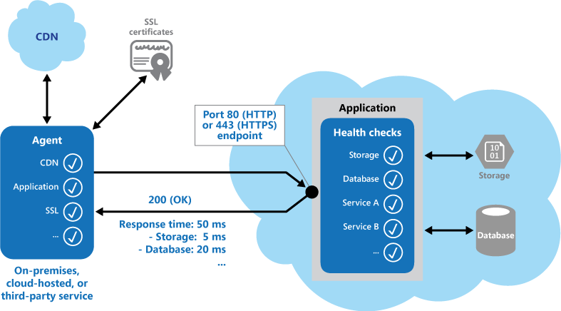
Other checks that might be carried out by the health monitoring code in the application include:
- Checking cloud storage or a database for availability and response time.
- Checking other resources or services located in the application, or located elsewhere but used by the application.
Services and tools are available that monitor web applications by submitting a request to a configurable set of endpoints, and evaluating the results against a set of configurable rules. It's relatively easy to create a service endpoint whose sole purpose is to perform some functional tests on the system.
Typical checks that can be performed by the monitoring tools include:
- Validating the response code. For example, an HTTP response of 200 (OK) indicates that the application responded without error. The monitoring system might also check for other response codes to give more comprehensive results.
- Checking the content of the response to detect errors, even when a 200 (OK) status code is returned. This can detect errors that affect only a section of the returned web page or service response. For example, checking the title of a page or looking for a specific phrase that indicates the correct page was returned.
- Measuring the response time, which indicates a combination of the network latency and the time that the application took to execute the request. An increasing value can indicate an emerging problem with the application or network.
- Checking resources or services located outside the application, such as a content delivery network used by the application to deliver content from global caches.
- Checking for expiration of SSL certificates.
- Measuring the response time of a DNS lookup for the URL of the application to measure DNS latency and DNS failures.
- Validating the URL returned by the DNS lookup to ensure correct entries. This can help to avoid malicious request redirection through a successful attack on the DNS server.
It's also useful, where possible, to run these checks from different on-premises or hosted locations to measure and compare response times. Ideally you should monitor applications from locations that are close to customers to get an accurate view of the performance from each location. In addition to providing a more robust checking mechanism, the results can help you decide on the deployment location for the application—and whether to deploy it in more than one datacenter.
Tests should also be run against all the service instances that customers use to ensure the application is working correctly for all customers. For example, if customer storage is spread across more than one storage account, the monitoring process should check all of these.
Issues and considerations
Consider the following points when deciding how to implement this pattern:
How to validate the response. For example, is just a single 200 (OK) status code sufficient to verify the application is working correctly? While this provides the most basic measure of application availability, and is the minimum implementation of this pattern, it provides little information about the operations, trends, and possible upcoming issues in the application.
Make sure that the application correctly returns a 200 (OK) only when the target resource is found and processed. In some scenarios, such as when using a master page to host the target web page, the server sends back a 200 (OK) status code instead of a 404 (Not Found) code, even when the target content page was not found.
The number of endpoints to expose for an application. One approach is to expose at least one endpoint for the core services that the application uses and another for lower priority services, allowing different levels of importance to be assigned to each monitoring result. Also consider exposing more endpoints, such as one for each core service, for additional monitoring granularity. For example, a health verification check might check the database, storage, and an external geocoding service that an application uses, with each requiring a different level of uptime and response time. The application could still be healthy if the geocoding service, or some other background task, is unavailable for a few minutes.
Whether to use the same endpoint for monitoring as is used for general access, but to a specific path designed for health verification checks, for example, /HealthCheck/{GUID}/ on the general access endpoint. This allows some functional tests in the application to be run by the monitoring tools, such as adding a new user registration, signing in, and placing a test order, while also verifying that the general access endpoint is available.
The type of information to collect in the service in response to monitoring requests, and how to return this information. Most existing tools and frameworks look only at the HTTP status code that the endpoint returns. To return and validate additional information, you might have to create a custom monitoring utility or service.
How much information to collect. Performing excessive processing during the check can overload the application and impact other users. The time it takes might exceed the timeout of the monitoring system so it marks the application as unavailable. Most applications include instrumentation such as error handlers and performance counters that log performance and detailed error information, this might be sufficient instead of returning additional information from a health verification check.
Caching the endpoint status. It could be expensive to run the health check too frequently. If the health status is reported through a dashboard, for example, you don't want every request from the dashboard to trigger a health check. Instead, periodically check the system health and cache the status. Expose an endpoint that returns the cached status.
How to configure security for the monitoring endpoints to protect them from public access, which might expose the application to malicious attacks, risk the exposure of sensitive information, or attract denial of service (DoS) attacks. Typically this should be done in the application configuration so that it can be updated easily without restarting the application. Consider using one or more of the following techniques:
- Secure the endpoint by requiring authentication. You can do this by using an authentication security key in the request header or by passing credentials with the request, provided that the monitoring service or tool supports authentication.
- Use an obscure or hidden endpoint. For example, expose the endpoint on a different IP address to that used by the default application URL, configure the endpoint on a standard HTTP port, and/or use a complex path to the test page. You can usually specify additional endpoint addresses and ports in the application configuration, and add entries for these endpoints to the DNS server if required to avoid having to specify the IP address directly.
- Expose a method on an endpoint that accepts a parameter such as a key value or an operation mode value. Depending on the value supplied for this parameter, when a request is received the code can perform a specific test or set of tests, or return a 404 (Not Found) error if the parameter value isn't recognized. The recognized parameter values could be set in the application configuration.
- DoS attacks are likely to have less impact on a separate endpoint that performs basic functional tests without compromising the operation of the application. Ideally, avoid using a test that might expose sensitive information. If you must return information that might be useful to an attacker, consider how you'll protect the endpoint and the data from unauthorized access. In this case just relying on obscurity isn't enough. You should also consider using an HTTPS connection and encrypting any sensitive data, although this will increase the load on the server.
- How to access an endpoint that's secured using authentication. Not all tools and frameworks can be configured to include credentials with the health verification request. For example, Microsoft Azure built-in health verification features can't provide authentication credentials. Some thirdparty alternatives are Pingdom, Panopta, NewRelic, and Statuscake.
- How to ensure that the monitoring agent is performing correctly. One approach is to expose an endpoint that simply returns a value from the application configuration or a random value that can be used to test the agent.
Also ensure that the monitoring system performs checks on itself, such as a self-test and built-in test, to avoid it issuing false positive results.
When to use this pattern
This pattern is useful for:
- Monitoring websites and web applications to verify availability. • Monitoring websites and web applications to check for correct operation.
- Monitoring middle-tier or shared services to detect and isolate a failure that could disrupt other applications.
- Complementing existing instrumentation in the application, such as performance counters and error handlers. Health verification checking doesn't replace the requirement for logging and auditing in the application. Instrumentation can provide valuable information for an existing framework that monitors counters and error logs to detect failures or other issues. However, it can't provide information if the application is unavailable.
Example
The following code examples, taken from the HealthCheckController class (a sample that demonstrates this pattern is available on GitHub), demonstrates exposing an endpoint for performing a range of health checks.
The CoreServices method, shown below in C#, performs a series of checks on services used in the application. If all of the tests run without error, the method returns a 200 (OK) status code. If any of the tests raises an exception, the method returns a 500 (Internal Error) status code. The method could optionally return additional information when an error occurs, if the monitoring tool or framework is able to make use of it.
public ActionResult CoreServices() {
try {
// Run a simple check to ensure the database is available.
DataStore.Instance.CoreHealthCheck();
// Run a simple check on our external service.
MyExternalService.Instance.CoreHealthCheck();
} catch (Exception ex) {
Trace.TraceError("Exception in basic health check: {
0
}", ex.Message);
// This can optionally return different status codes based on the exception.
// Optionally it could return more details about the exception.
// The additional information could be used by administrators who access the
// endpoint with a browser, or using a ping utility that can display the
// additional information.
return new HttpStatusCodeResult((int) HttpStatusCode.InternalServerError);
}
return new HttpStatusCodeResult((int) HttpStatusCode.OK);
}
The ObscurePath method shows how you can read a path from the application configuration and use it as the endpoint for tests. This example, in C#, also shows how you can accept an ID as a parameter and use it to check for valid requests.
public ActionResult ObscurePath(string id) {
// The id could be used as a simple way to obscure or hide the endpoint.
// The id to match could be retrieved from configuration and, if matched,
// perform a specific set of tests and return the result. If not matched it
// could return a 404 (Not Found) status.
// The obscure path can be set through configuration to hide the endpoint.
var hiddenPathKey = CloudConfigurationManager.GetSetting("Test.ObscurePath");
// If the value passed does not match that in configuration, return 404 (Not Found).
if (!string.Equals(id, hiddenPathKey)) {
return new HttpStatusCodeResult((int) HttpStatusCode.NotFound);
}
// Else continue and run the tests...
// Return results from the core services test.
return this.CoreServices();
}
The TestResponseFromConfig method shows how you can expose an endpoint that performs a check for a specified configuration setting value.
public ActionResult TestResponseFromConfig() {
// Health check that returns a response code set in configuration for testing.
var returnStatusCodeSetting = CloudConfigurationManager.GetSetting("Test.ReturnStatusCode");
int returnStatusCode;
if (!int.TryParse(returnStatusCodeSetting, out returnStatusCode)) {
returnStatusCode = (int) HttpStatusCode.OK;
}
return new HttpStatusCodeResult(returnStatusCode);
}
Monitoring endpoints in Azure hosted applications
Some options for monitoring endpoints in Azure applications are:
- Use the built-in monitoring features of Azure.
- Use a third-party service or a framework such as Microsoft System Center Operations Manager.
- Create a custom utility or a service that runs on your own or on a hosted server.
Even though Azure provides a reasonably comprehensive set of monitoring options, you can use additional services and tools to provide extra information. Azure Management Services provides a built-in monitoring mechanism for alert rules. The alerts section of the management services page in the Azure portal allows you to configure up to ten alert rules per subscription for your services. These rules specify a condition and a threshold value for a service such as CPU load, or the number of requests or errors per second, and the service can automatically send email notifications to addresses you define in each rule.
The conditions you can monitor vary depending on the hosting mechanism you choose for your application (such as Web Sites, Cloud Services, Virtual Machines, or Mobile Services), but all of these include the ability to create an alert rule that uses a web endpoint you specify in the settings for your service. This endpoint should respond in a timely way so that the alert system can detect that the application is operating correctly.
Read more information about creating alert notifications.
If you host your application in Azure Cloud Services web and worker roles or Virtual Machines, you can take advantage of one of the built-in services in Azure called Traffic Manager. Traffic Manager is a routing and load-balancing service that can distribute requests to specific instances of your Cloud Services hosted application based on a range of rules and settings.
In addition to routing requests, Traffic Manager pings a URL, port, and relative path that you specify on a regular basis to determine which instances of the application defined in its rules are active and are responding to requests. If it detects a status code 200 (OK), it marks the application as available. Any other status code causes Traffic Manager to mark the application as offline. You can view the status in the Traffic Manager console, and configure the rule to reroute requests to other instances of the application that are responding.
However, Traffic Manager will only wait ten seconds to receive a response from the monitoring URL. Therefore, you should ensure that your health verification code executes in this time, allowing for network latency for the round trip from Traffic Manager to your application and back again.
Read more information about using Traffic Manager to monitor your applications. Traffic Manager is also discussed in Multiple Datacenter Deployment Guidance.
Related guidance
The following guidance can be useful when implementing this pattern:
- Instrumentation and Telemetry Guidance. Checking the health of services and components is typically done by probing, but it's also useful to have information in place to monitor application performance and detect events that occur at runtime. This data can be transmitted back to monitoring tools as additional information for health monitoring. Instrumentation and Telemetry Guidance explores gathering remote diagnostics information that's collected by instrumentation in applications.
- Receiving alert notifications.
- This pattern includes a downloadable sample application.
Index Table pattern
Create indexes over the fields in data stores that are frequently referenced by queries. This pattern can improve query performance by allowing applications to more quickly locate the data to retrieve from a data store.
Context and problem
Many data stores organize the data for a collection of entities using the primary key. An application can use this key to locate and retrieve data. The figure shows an example of a data store holding customer information. The primary key is the Customer ID. The figure shows customer information organized by the primary key (Customer ID).

While the primary key is valuable for queries that fetch data based on the value of this key, an application might not be able to use the primary key if it needs to retrieve data based on some other field. In the customers example, an application can't use the Customer ID primary key to retrieve customers if it queries data solely by referencing the value of some other attribute, such as the town in which the customer is located. To perform a query such as this, the application might have to fetch and examine every customer record, which could be a slow process.
Many relational database management systems support secondary indexes. A secondary index is a separate data structure that's organized by one or more nonprimary (secondary) key fields, and it indicates where the data for each indexed value is stored. The items in a secondary index are typically sorted by the value of the secondary keys to enable fast lookup of data. These indexes are usually maintained automatically by the database management system.
You can create as many secondary indexes as you need to support the different queries that your application performs. For example, in a Customers table in a relational database where the Customer ID is the primary key, it's beneficial to add a secondary index over the town field if the application frequently looks up customers by the town where they reside.
However, although secondary indexes are common in relational systems, most NoSQL data stores used by cloud applications don't provide an equivalent feature.
Solution
If the data store doesn't support secondary indexes, you can emulate them manually by creating your own index tables. An index table organizes the data by a specified key. Three strategies are commonly used for structuring an index table, depending on the number of secondary indexes that are required and the nature of the queries that an application performs.
The first strategy is to duplicate the data in each index table but organize it by different keys (complete denormalization). The next figure shows index tables that organize the same customer information by Town and LastName.
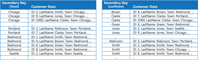
This strategy is appropriate if the data is relatively static compared to the number of times it's queried using each key. If the data is more dynamic, the processing overhead of maintaining each index table becomes too large for this approach to be useful. Also, if the volume of data is very large, the amount of space required to store the duplicate data is significant.
The second strategy is to create normalized index tables organized by different keys and reference the original data by using the primary key rather than duplicating it, as shown in the following figure. The original data is called a fact table.

This technique saves space and reduces the overhead of maintaining duplicate data. The disadvantage is that an application has to perform two lookup operations to find data using a secondary key. It has to find the primary key for the data in the index table, and then use the primary key to look up the data in the fact table.
The third strategy is to create partially normalized index tables organized by different keys that duplicate frequently retrieved fields. Reference the fact table to access less frequently accessed fields. The next figure shows how commonly accessed data is duplicated in each index table.

With this strategy, you can strike a balance between the first two approaches. The data for common queries can be retrieved quickly by using a single lookup, while the space and maintenance overhead isn't as significant as duplicating the entire data set.
If an application frequently queries data by specifying a combination of values (for example, "Find all customers that live in Redmond and that have a last name of Smith"), you could implement the keys to the items in the index table as a concatenation of the Town attribute and the LastName attribute. The next figure shows an index table based on composite keys. The keys are sorted by Town, and then by LastName for records that have the same value for Town.

Index tables can speed up query operations over sharded data, and are especially useful where the shard key is hashed. The next figure shows an example where the shard key is a hash of the Customer ID. The index table can organize data by the nonhashed value (Town and LastName), and provide the hashed shard key as the lookup data. This can save the application from repeatedly calculating hash keys (an expensive operation) if it needs to retrieve data that falls within a range, or it needs to fetch data in order of the nonhashed key. For example, a query such as "Find all customers that live in Redmond" can be quickly resolved by locating the matching items in the index table, where they're all stored in a contiguous block. Then, follow the references to the customer data using the shard keys stored in the index table.

Issues and considerations
Consider the following points when deciding how to implement this pattern:
- The overhead of maintaining secondary indexes can be significant. You must analyze and understand the queries that your application uses. Only create index tables when they're likely to be used regularly. Don't create speculative index tables to support queries that an application doesn't perform, or performs only occasionally.
- Duplicating data in an index table can add significant overhead in storage costs and the effort required to maintain multiple copies of data.
- Implementing an index table as a normalized structure that references the original data requires an application to perform two lookup operations to find data. The first operation searches the index table to retrieve the primary key, and the second uses the primary key to fetch the data.
- If a system incorporates a number of index tables over very large data sets, it can be difficult to maintain consistency between index tables and the original data. It might be possible to design the application around the eventual consistency model. For example, to insert, update, or delete data, an application could post a message to a queue and let a separate task perform the operation and maintain the index tables that reference this data asynchronously. For more information about implementing eventual consistency, see the Data Consistency Primer.
- Microsoft Azure storage tables support transactional updates for changes made to data held in the same partition (referred to as entity group transactions). If you can store the data for a fact table and one or more index tables in the same partition, you can use this feature to help ensure consistency.
- Index tables might themselves be partitioned or sharded.
When to use this pattern
Use this pattern to improve query performance when an application frequently needs to retrieve data by using a key other than the primary (or shard) key.
This pattern might not be useful when:
- Data is volatile. An index table can become out of date very quickly, making it ineffective or making the overhead of maintaining the index table greater than any savings made by using it. • A field selected as the secondary key for an index table is nondiscriminating and can only have a small set of values (for example, gender).
- The balance of the data values for a field selected as the secondary key for an index table are highly skewed. For example, if 90% of the records contain the same value in a field, then creating and maintaining an index table to look up data based on this field might create more overhead than scanning sequentially through the data. However, if queries very frequently target values that lie in the remaining 10%, this index can be useful. You should understand the queries that your application is performing, and how frequently they're performed.
Example
Azure storage tables provide a highly scalable key/value data store for applications running in the cloud. Applications store and retrieve data values by specifying a key. The data values can contain multiple fields, but the structure of a data item is opaque to table storage, which simply handles a data item as an array of bytes.
Azure storage tables also support sharding. The sharding key includes two elements, a partition key and a row key. Items that have the same partition key are stored in the same partition (shard), and the items are stored in row key order within a shard. Table storage is optimized for performing queries that fetch data falling within a contiguous range of row key values within a partition. If you're building cloud applications that store information in Azure tables, you should structure your data with this feature in mind.
For example, consider an application that stores information about movies. The application frequently queries movies by genre (action, documentary, historical, comedy, drama, and so on). You could create an Azure table with partitions for each genre by using the genre as the partition key, and specifying the movie name as the row key, as shown in the next figure.

This approach is less effective if the application also needs to query movies by starring actor. In this case, you can create a separate Azure table that acts as an index table. The partition key is the actor and the row key is the movie name. The data for each actor will be stored in separate partitions. If a movie stars more than one actor, the same movie will occur in multiple partitions.
You can duplicate the movie data in the values held by each partition by adopting the first approach described in the Solution section above. However, it's likely that each movie will be replicated several times (once for each actor), so it might be more efficient to partially denormalize the data to support the most common queries (such as the names of the other actors) and enable an application to retrieve any remaining details by including the partition key necessary to find the complete information in the genre partitions. This approach is described by the third option in the Solution section. The next figure shows this approach.

Related patterns and guidance
The following patterns and guidance might also be relevant when implementing this pattern:
- Data Consistency Primer. An index table must be maintained as the data that it indexes changes. In the cloud, it might not be possible or appropriate to perform operations that update an index as part of the same transaction that modifies the data. In that case, an eventually consistent approach is more suitable. Provides information on the issues surrounding eventual consistency.
- Sharding pattern. The Index Table pattern is frequently used in conjunction with data partitioned by using shards. The Sharding pattern provides more information on how to divide a data store into a set of shards.
- Materialized View pattern. Instead of indexing data to support queries that summarize data, it might be more appropriate to create a materialized view of the data. Describes how to support efficient summary queries by generating prepopulated views over data.
Leader Election pattern
Coordinate the actions performed by a collection of collaborating instances in a distributed application by electing one instance as the leader that assumes responsibility for managing the others. This can help to ensure that instances don't conflict with each other, cause contention for shared resources, or inadvertently interfere with the work that other instances are performing.
Context and problem
A typical cloud application has many tasks acting in a coordinated manner. These tasks could all be instances running the same code and requiring access to the same resources, or they might be working together in parallel to perform the individual parts of a complex calculation.
The task instances might run separately for much of the time, but it might also be necessary to coordinate the actions of each instance to ensure that they don't conflict, cause contention for shared resources, or accidentally interfere with the work that other task instances are performing.
For example:
- In a cloud-based system that implements horizontal scaling, multiple instances of the same task could be running at the same time with each instance serving a different user. If these instances write to a shared resource, it's necessary to coordinate their actions to prevent each instance from overwriting the changes made by the others.
- If the tasks are performing individual elements of a complex calculation in parallel, the results need to be aggregated when they all complete.
The task instances are all peers, so there isn't a natural leader that can act as the coordinator or aggregator.
Solution
A single task instance should be elected to act as the leader, and this instance should coordinate the actions of the other subordinate task instances. If all of the task instances are running the same code, they are each capable of acting as the leader. Therefore, the election process must be managed carefully to prevent two or more instances taking over the leader role at the same time.
The system must provide a robust mechanism for selecting the leader. This method has to cope with events such as network outages or process failures. In many solutions, the subordinate task instances monitor the leader through some type of heartbeat method, or by polling. If the designated leader terminates unexpectedly, or a network failure makes the leader unavailable to the subordinate task instances, it's necessary for them to elect a new leader.
There are several strategies for electing a leader among a set of tasks in a distributed environment, including:
- Selecting the task instance with the lowest-ranked instance or process ID.
- Racing to acquire a shared, distributed mutex. The first task instance that acquires the mutex is the leader. However, the system must ensure that, if the leader terminates or becomes disconnected from the rest of the system, the mutex is released to allow another task instance to become the leader.
- Implementing one of the common leader election algorithms such as the Bully Algorithm or the Ring Algorithm. These algorithms assume that each candidate in the election has a unique ID, and that it can communicate with the other candidates reliably.
Issues and considerations
Consider the following points when deciding how to implement this pattern:
- The process of electing a leader should be resilient to transient and persistent failures.
- It must be possible to detect when the leader has failed or has become otherwise unavailable (such as due to a communications failure). How quickly detection is needed is system dependent. Some systems might be able to function for a short time without a leader, during which a transient fault might be fixed. In other cases, it might be necessary to detect leader failure immediately and trigger a new election.
- In a system that implements horizontal autoscaling, the leader could be terminated if the system scales back and shuts down some of the computing resources.
- Using a shared, distributed mutex introduces a dependency on the external service that provides the mutex. The service constitutes a single point of failure. If it becomes unavailable for any reason, the system won't be able to elect a leader.
- Using a single dedicated process as the leader is a straightforward approach. However, if the process fails there could be a significant delay while it's restarted. The resulting latency can affect the performance and response times of other processes if they're waiting for the leader to coordinate an operation.
- Implementing one of the leader election algorithms manually provides the greatest flexibility for tuning and optimizing the code.
When to use this pattern
Use this pattern when the tasks in a distributed application, such as a cloud-hosted solution, need careful coordination and there's no natural leader.
Avoid making the leader a bottleneck in the system. The purpose of the leader is to coordinate the work of the subordinate tasks, and it doesn't necessarily have to participate in this work itself— although it should be able to do so if the task isn't elected as the leader.
This pattern might not be useful if:
- There's a natural leader or dedicated process that can always act as the leader. For example, it might be possible to implement a singleton process that coordinates thea task instances. If this process fails or becomes unhealthy, the system can shut it down and restart it.
- The coordination between tasks can be achieved using a more lightweight method. For example, if several task instances simply need coordinated access to a shared resource, a better solution is to use optimistic or pessimistic locking to control access.
- A third-party solution is more appropriate. For example, the Microsoft Azure HDInsight service (based on Apache Hadoop) uses the services provided by Apache Zookeeper to coordinate the map and reduce tasks that collect and summarize data.
Example
The DistributedMutex project in the LeaderElection solution (a sample that demonstrates this pattern is available on GitHub) shows how to use a lease on an Azure Storage blob to provide a mechanism for implementing a shared, distributed mutex. This mutex can be used to elect a leader among a group of role instances in an Azure cloud service. The first role instance to acquire the lease is elected the leader, and remains the leader until it releases the lease or isn't able to renew the lease. Other role instances can continue to monitor the blob lease in case the leader is no longer available.
A blob lease is an exclusive write lock over a blob. A single blob can be the subject of only one lease at any point in time. A role instance can request a lease over a specified blob, and it'll be granted the lease if no other role instance holds a lease over the same blob. Otherwise the request will throw an exception.
To avoid a faulted role instance retaining the lease indefinitely, specify a lifetime for the lease. When this expires, the lease becomes available. However, while a role instance holds the lease it can request that the lease is renewed, and it'll be granted the lease for a further period of time. The role instance can continually repeat this process if it wants to retain the lease. For more information on how to lease a blob, see Lease Blob (REST API).
The BlobDistributedMutex class in the C# example below contains the RunTaskWhenMutexAquired method that enables a role instance to attempt to acquire a lease over a specified blob. The details of the blob (the name, container, and storage account) are passed to the constructor in a BlobSettings object when the BlobDistributedMutex object is created (this object is a simple struct that is included in the sample code). The constructor also accepts a Task that references the code that the role instance should run if it successfully acquires the lease over the blob and is elected the leader. Note that the code that handles the low-level details of acquiring the lease is implemented in a separate helper class named BlobLeaseManager.
public class BlobDistributedMutex {
...
private readonly BlobSettings blobSettings;
private readonly Func < CancellationToken, Task > taskToRunWhenLeaseAcquired;
...
public BlobDistributedMutex(BlobSettings blobSettings,
Func < CancellationToken, Task > taskToRunWhenLeaseAquired) {
this.blobSettings = blobSettings;
this.taskToRunWhenLeaseAquired = taskToRunWhenLeaseAquired;
}
public async Task RunTaskWhenMutexAcquired(CancellationToken token) {
var leaseManager = new BlobLeaseManager(blobSettings);
await this.RunTaskWhenBlobLeaseAcquired(leaseManager, token);
}
...
The RunTaskWhenMutexAquired method in the code sample above invokes the RunTaskWhenBlobLeaseAcquired method shown in the following code sample to actually acquire the lease. The RunTaskWhenBlobLeaseAcquired method runs asynchronously. If the lease is successfully acquired, the role instance has been elected the leader. The purpose of the taskToRunWhenLeaseAcquired delegate is to perform the work that coordinates the other role instances. If the lease isn't acquired, another role instance has been elected as the leader and the current role instance remains a subordinate. Note that the TryAcquireLeaseOrWait method is a helper method that uses the BlobLeaseManager object to acquire the lease.
private async Task RunTaskWhenBlobLeaseAcquired(
BlobLeaseManager leaseManager, CancellationToken token) {
while (!token.IsCancellationRequested) {
// Try to acquire the blob lease.
// Otherwise wait for a short time before trying again.
string leaseId = await this.TryAquireLeaseOrWait(leaseManager, token);
if (!string.IsNullOrEmpty(leaseId)) {
// Create a new linked cancellation token source so that if either the
// original token is canceled or the lease can't be renewed, the
// leader task can be canceled.
using(var leaseCts =
CancellationTokenSource.CreateLinkedTokenSource(new [] {
token
})) {
// Run the leader task.
var leaderTask = this.taskToRunWhenLeaseAquired.Invoke(leaseCts.Token);
...
}
}
}
...
}
The task started by the leader also runs asynchronously. While this task is running, the RunTaskWhenBlobLeaseAquired method shown in the following code sample periodically attempts to renew the lease. This helps to ensure that the role instance remains the leader. In the sample solution, the delay between renewal requests is less than the time specified for the duration of the lease in order to prevent another role instance from being elected the leader. If the renewal fails for any reason, the task is canceled.
If the lease fails to be renewed or the task is canceled (possibly as a result of the role instance shutting down), the lease is released. At this point, this or another role instance might be elected as the leader. The code extract below shows this part of the process.
private async Task RunTaskWhenBlobLeaseAcquired(
BlobLeaseManager leaseManager, CancellationToken token) {
while (...) {
...
if (...) {
...
using(var leaseCts = ...) {
...
// Keep renewing the lease in regular intervals.
// If the lease can't be renewed, then the task completes.
var renewLeaseTask =
this.KeepRenewingLease(leaseManager, leaseId, leaseCts.Token);
// When any task completes (either the leader task itself or when it
// couldn't renew the lease) then cancel the other task.
await CancelAllWhenAnyCompletes(leaderTask, renewLeaseTask, leaseCts);
}
}
}
}
...
}
The KeepRenewingLease method is another helper method that uses the BlobLeaseManager object to renew the lease. The CancelAllWhenAnyCompletes method cancels the tasks specified as the first two parameters. The following diagram illustrates using the BlobDistributedMutex class to elect a leader and run a task that coordinates operations.

The following code example shows how to use the BlobDistributedMutex class in a worker role. This code acquires a lease over a blob named MyLeaderCoordinatorTask in the lease's container in development storage, and specifies that the code defined in the MyLeaderCoordinatorTask method should run if the role instance is elected the leader.
var settings = new BlobSettings(CloudStorageAccount.DevelopmentStorageAccount, "leases", "MyLeaderCoordinatorTask"); var cts = new CancellationTokenSource();
var mutex = new BlobDistributedMutex(settings, MyLeaderCoordinatorTask); mutex.RunTaskWhenMutexAcquired(this.cts.Token);
...
// Method that runs if the role instance is elected the leader
private static async Task MyLeaderCoordinatorTask(CancellationToken token) {
...
}
Note the following points about the sample solution:
- The blob is a potential single point of failure. If the blob service becomes unavailable, or is inaccessible, the leader won't be able to renew the lease and no other role instance will be able to acquire the lease. In this case, no role instance will be able to act as the leader. However, the blob service is designed to be resilient, so complete failure of the blob service is considered to be extremely unlikely.
- If the task being performed by the leader stalls, the leader might continue to renew the lease, preventing any other role instance from acquiring the lease and taking over the leader role in order to coordinate tasks. In the real world, the health of the leader should be checked at frequent intervals.
- The election process is nondeterministic. You can't make any assumptions about which role instance will acquire the blob lease and become the leader.
- The blob used as the target of the blob lease shouldn't be used for any other purpose. If a role instance attempts to store data in this blob, this data won't be accessible unless the role instance is the leader and holds the blob lease.
Related patterns and guidance
The following guidance might also be relevant when implementing this pattern:
- This pattern has a downloadable sample application.
- Autoscaling Guidance. It's possible to start and stop instances of the task hosts as the load on the application varies. Autoscaling can help to maintain throughput and performance during times of peak processing.
- Compute Partitioning Guidance. This guidance describes how to allocate tasks to hosts in a cloud service in a way that helps to minimize running costs while maintaining the scalability, performance, availability, and security of the service.
- The Task-based Asynchronous Pattern.
- An example illustrating the Bully Algorithm.
- An example illustrating the Ring Algorithm.
- Apache Curator a client library for Apache ZooKeeper.
- The article Lease Blob (REST API) on MSDN.
Materialized View pattern
Generate prepopulated views over the data in one or more data stores when the data isn't ideally formatted for required query operations. This can help support efficient querying and data extraction, and improve application performance.
Context and problem
When storing data, the priority for developers and data administrators is often focused on how the data is stored, as opposed to how it's read. The chosen storage format is usually closely related to the format of the data, requirements for managing data size and data integrity, and the kind of store in use. For example, when using NoSQL document store, the data is often represented as a series of aggregates, each containing all of the information for that entity.
However, this can have a negative effect on queries. When a query only needs a subset of the data from some entities, such as a summary of orders for several customers without all of the order details, it must extract all of the data for the relevant entities in order to obtain the required information.
Solution
To support efficient querying, a common solution is to generate, in advance, a view that materializes the data in a format suited to the required results set. The Materialized View pattern describes generating prepopulated views of data in environments where the source data isn't in a suitable format for querying, where generating a suitable query is difficult, or where query performance is poor due to the nature of the data or the data store.
These materialized views, which only contain data required by a query, allow applications to quickly obtain the information they need. In addition to joining tables or combining data entities, materialized views can include the current values of calculated columns or data items, the results of combining values or executing transformations on the data items, and values specified as part of the query. A materialized view can even be optimized for just a single query.
A key point is that a materialized view and the data it contains is completely disposable because it can be entirely rebuilt from the source data stores. A materialized view is never updated directly by an application, and so it's a specialized cache.
When the source data for the view changes, the view must be updated to include the new information. You can schedule this to happen automatically, or when the system detects a change to the original data. In some cases it might be necessary to regenerate the view manually. The figure shows an example of how the Materialized View pattern might be used.
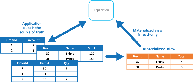
Issues and considerations
Consider the following points when deciding how to implement this pattern:
How and when the view will be updated. Ideally it'll regenerate in response to an event indicating a change to the source data, although this can lead to excessive overhead if the source data changes rapidly. Alternatively, consider using a scheduled task, an external trigger, or a manual action to regenerate the view.
In some systems, such as when using the Event Sourcing pattern to maintain a store of only the events that modified the data, materialized views are necessary. Prepopulating views by examining all events to determine the current state might be the only way to obtain information from the event store. If you're not using Event Sourcing, you need to consider whether a materialized view is helpful or not. Materialized views tend to be specifically tailored to one, or a small number of queries. If many queries are used, materialized views can result in unacceptable storage capacity requirements and storage cost.
Consider the impact on data consistency when generating the view, and when updating the view if this occurs on a schedule. If the source data is changing at the point when the view is generated, the copy of the data in the view won't be fully consistent with the original data.
Consider where you'll store the view. The view doesn't have to be located in the same store or partition as the original data. It can be a subset from a few different partitions combined.
A view can be rebuilt if lost. Because of that, if the view is transient and is only used to improve query performance by reflecting the current state of the data, or to improve scalability, it can be stored in a cache or in a less reliable location.
When defining a materialized view, maximize its value by adding data items or columns to it based on computation or transformation of existing data items, on values passed in the query, or on combinations of these values when appropriate.
Where the storage mechanism supports it, consider indexing the materialized view to further increase performance. Most relational databases support indexing for views, as do big data solutions based on Apache Hadoop.
When to use this pattern
This pattern is useful when:
- Creating materialized views over data that's difficult to query directly, or where queries must be very complex to extract data that's stored in a normalized, semi-structured, or unstructured way. • Creating temporary views that can dramatically improve query performance, or can act directly as source views or data transfer objects for the UI, for reporting, or for display.
- Supporting occasionally connected or disconnected scenarios where connection to the data store isn't always available. The view can be cached locally in this case.
- Simplifying queries and exposing data for experimentation in a way that doesn't require knowledge of the source data format. For example, by joining different tables in one or more databases, or one or more domains in NoSQL stores, and then formatting the data to fit its eventual use.
- Providing access to specific subsets of the source data that, for security or privacy reasons, shouldn't be generally accessible, open to modification, or fully exposed to users.
- Bridging different data stores, to take advantage of their individual capabilities. For example, using a cloud store that's efficient for writing as the reference data store, and a relational database that offers good query and read performance to hold the materialized views.
This pattern isn't useful in the following situations:
- The source data is simple and easy to query.
- The source data changes very quickly, or can be accessed without using a view. In these cases, you should avoid the processing overhead of creating views.
- Consistency is a high priority. The views might not always be fully consistent with the original data.
Example
The following figure shows an example of using the Materialized View pattern to generate a summary of sales. Data in the Order, OrderItem, and Customer tables in separate partitions in an Azure storage account are combined to generate a view containing the total sales value for each product in the Electronics category, along with a count of the number of customers who made purchases of each item.
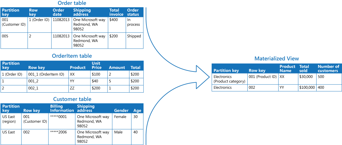
Creating this materialized view requires complex queries. However, by exposing the query result as a materialized view, users can easily obtain the results and use them directly or incorporate them in another query. The view is likely to be used in a reporting system or dashboard, and can be updated on a scheduled basis such as weekly.
Although this example utilizes Azure table storage, many relational database management systems also provide native support for materialized views.
Related patterns and guidance
The following patterns and guidance might also be relevant when implementing this pattern:
- Data Consistency Primer. The summary information in a materialized view has to be maintained so that it reflects the underlying data values. As the data values change, it might not be practical to update the summary data in real time, and instead you'll have to adopt an eventually consistent approach. Summarizes the issues surrounding maintaining consistency over distributed data, and describes the benefits and tradeoffs of different consistency models.
- Command and Query Responsibility Segregation (CQRS) pattern. Use to update the information in a materialized view by responding to events that occur when the underlying data values change.
- Event Sourcing pattern. Use in conjunction with the CQRS pattern to maintain the information in a materialized view. When the data values a materialized view is based on are changed, the system can raise events that describe these changes and save them in an event store.
- Index Table pattern. The data in a materialized view is typically organized by a primary key, but queries might need to retrieve information from this view by examining data in other fields. Use to create secondary indexes over data sets for data stores that don't support native secondary indexes.
Pipes and Filters pattern
Decompose a task that performs complex processing into a series of separate elements that can be reused. This can improve performance, scalability, and reusability by allowing task elements that perform the processing to be deployed and scaled independently.
Context and problem
An application is required to perform a variety of tasks of varying complexity on the information that it processes. A straightforward but inflexible approach to implementing an application is to perform this processing as a monolithic module. However, this approach is likely to reduce the opportunities for refactoring the code, optimizing it, or reusing it if parts of the same processing are required elsewhere within the application.
The figure illustrates the issues with processing data using the monolithic approach. An application receives and processes data from two sources. The data from each source is processed by a separate module that performs a series of tasks to transform this data, before passing the result to the business logic of the application.

Some of the tasks that the monolithic modules perform are functionally very similar, but the modules have been designed separately. The code that implements the tasks is closely coupled in a module, and has been developed with little or no thought given to reuse or scalability.
However, the processing tasks performed by each module, or the deployment requirements for each task, could change as business requirements are updated. Some tasks might be compute intensive and could benefit from running on powerful hardware, while others might not require such expensive resources. Also, additional processing might be required in the future, or the order in which the tasks performed by the processing could change. A solution is required that addresses these issues, and increases the possibilities for code reuse.
Solution
Break down the processing required for each stream into a set of separate components (or filters), each performing a single task. By standardizing the format of the data that each component receives and sends, these filters can be combined together into a pipeline. This helps to avoid duplicating code, and makes it easy to remove, replace, or integrate additional components if the processing requirements change. The next figure shows a solution implemented using pipes and filters.

The time it takes to process a single request depends on the speed of the slowest filter in the pipeline. One or more filters could be a bottleneck, especially if a large number of requests appear in a stream from a particular data source. A key advantage of the pipeline structure is that it provides opportunities for running parallel instances of slow filters, enabling the system to spread the load and improve throughput.
The filters that make up a pipeline can run on different machines, enabling them to be scaled independently and take advantage of the elasticity that many cloud environments provide. A filter that is computationally intensive can run on high performance hardware, while other less demanding filters can be hosted on less expensive commodity hardware. The filters don't even have to be in the same data center or geographical location, which allows each element in a pipeline to run in an environment that is close to the resources it requires. The next figure shows an example applied to the pipeline for the data from Source 1.

If the input and output of a filter are structured as a stream, it's possible to perform the processing for each filter in parallel. The first filter in the pipeline can start its work and output its results, which are passed directly on to the next filter in the sequence before the first filter has completed its work.
Another benefit is the resiliency that this model can provide. If a filter fails or the machine it's running on is no longer available, the pipeline can reschedule the work that the filter was performing and direct this work to another instance of the component. Failure of a single filter doesn't necessarily result in failure of the entire pipeline.
Using the Pipes and Filters pattern in conjunction with the Compensating Transaction pattern is an alternative approach to implementing distributed transactions. A distributed transaction can be broken down into separate, compensable tasks, each of which can be implemented by using a filter that also implements the Compensating Transaction pattern. The filters in a pipeline can be implemented as separate hosted tasks running close to the data that they maintain.
Issues and considerations
You should consider the following points when deciding how to implement this pattern:
- Complexity. The increased flexibility that this pattern provides can also introduce complexity, especially if the filters in a pipeline are distributed across different servers.
- Reliability. Use an infrastructure that ensures that data flowing between filters in a pipeline won't be lost.
- Idempotency. If a filter in a pipeline fails after receiving a message and the work is rescheduled to another instance of the filter, part of the work might have already been completed. If this work updates some aspect of the global state (such as information stored in a database), the same update could be repeated. A similar issue might occur if a filter fails after posting its results to the next filter in the pipeline, but before indicating that it's completed its work successfully. In these cases, the same work could be repeated by another instance of the filter, causing the same results to be posted twice. This could result in subsequent filters in the pipeline processing the same data twice. Therefore filters in a pipeline should be designed to be idempotent. For more information see Idempotency Patterns on Jonathan Oliver's blog.
- Repeated messages. If a filter in a pipeline fails after posting a message to the next stage of the pipeline, another instance of the filter might be run, and it'll post a copy of the same message to the pipeline. This could cause two instances of the same message to be passed to the next filter. To avoid this, the pipeline should detect and eliminate duplicate messages. If you're implementing the pipeline by using message queues (such as Microsoft Azure Service Bus queues), the message queuing infrastructure might provide automatic duplicate message detection and removal.
- Context and state. In a pipeline, each filter essentially runs in isolation and shouldn't make any assumptions about how it was invoked. This means that each filter should be provided with sufficient context to perform its work. This context could include a large amount of state information.
When to use this pattern
Use this pattern when:
- The processing required by an application can easily be broken down into a set of independent steps. • The processing steps performed by an application have different scalability requirements. It's possible to group filters that should scale together in the same process. For more information, see the Compute Resource Consolidation pattern.
- Flexibility is required to allow reordering of the processing steps performed by an application, or the capability to add and remove steps.
- The system can benefit from distributing the processing for steps across different servers.
- A reliable solution is required that minimizes the effects of failure in a step while data is being processed.
This pattern might not be useful when:
- The processing steps performed by an application aren't independent, or they have to be performed together as part of the same transaction.
- The amount of context or state information required by a step makes this approach inefficient. It might be possible to persist state information to a database instead, but don't use this strategy if the additional load on the database causes excessive contention.
Example
You can use a sequence of message queues to provide the infrastructure required to implement a pipeline. An initial message queue receives unprocessed messages. A component implemented as a filter task listens for a message on this queue, performs its work, and then posts the transformed message to the next queue in the sequence. Another filter task can listen for messages on this queue, process them, post the results to another queue, and so on until the fully transformed data appears in the final message in the queue. The next figure illustrates implementing a pipeline using message queues.

If you're building a solution on Azure you can use Service Bus queues to provide a reliable and scalable queuing mechanism. The ServiceBusPipeFilter class shown below in C# demonstrates how you can implement a filter that receives input messages from a queue, processes these messages, and posts the results to another queue.
The ServiceBusPipeFilter class is defined in the PipesAndFilters.Shared project available from GitHub.
public class ServiceBusPipeFilter {
...
private readonly string inQueuePath;
private readonly string outQueuePath;
...
private QueueClient inQueue;
private QueueClient outQueue;
...
public ServiceBusPipeFilter(..., string inQueuePath, string outQueuePath = null) {
...
this.inQueuePath = inQueuePath;
this.outQueuePath = outQueuePath;
}
public void Start() {
...
// Create the outbound filter queue if it doesn't exist.
...
this.outQueue = QueueClient.CreateFromConnectionString(...);
...
// Create the inbound and outbound queue clients.
this.inQueue = QueueClient.CreateFromConnectionString(...);
}
public void OnPipeFilterMessageAsync(
Func < BrokeredMessage, Task < BrokeredMessage >> asyncFilterTask, ...) {
...
this.inQueue.OnMessageAsync(
async(msg) => {
...
// Process the filter and send the output to the
// next queue in the pipeline.
var outMessage = await asyncFilterTask(msg);
// Send the message from the filter processor
// to the next queue in the pipeline.
if (outQueue != null) {
await outQueue.SendAsync(outMessage);
}
// Note: There's a chance that the same message could be sent twice
// or that a message gets processed by an upstream or downstream
// filter at the same time.
// This would happen in a situation where processing of a message was
// completed, it was sent to the next pipe/queue, and then failed
// to complete when using the PeekLock method.
// Idempotent message processing and concurrency should be considered
// in a real-world implementation.
},
options);
}
public async Task Close(TimeSpan timespan) {
// Pause the processing threads.
this.pauseProcessingEvent.Reset();
// There's no clean approach for waiting for the threads to complete
// the processing. This example simply stops any new processing, waits
// for the existing thread to complete, then closes the message pump
// and finally returns.
s Thread.Sleep(timespan);
this.inQueue.Close();
...
}
The Start method in the ServiceBusPipeFilter class connects to a pair of input and output queues, and the Close method disconnects from the input queue. The OnPipeFilterMessageAsync method performs the actual processing of messages, the asyncFilterTask parameter to this method specifies the processing to be performed. The OnPipeFilterMessageAsync method waits for incoming messages on the input queue, runs the code specified by the asyncFilterTask parameter over each message as it arrives, and posts the results to the output queue. The queues themselves are specified by the constructor.
The sample solution implements filters in a set of worker roles. Each worker role can be scaled independently, depending on the complexity of the business processing that it performs or the resources required for processing. Additionally, multiple instances of each worker role can be run in parallel to improve throughput.
The following code shows an Azure worker role named PipeFilterARoleEntry, defined in the PipeFilterA project in the sample solution.
public class PipeFilterARoleEntry: RoleEntryPoint {
...
private ServiceBusPipeFilter pipeFilterA;
public override bool OnStart() {
...
this.pipeFilterA = new ServiceBusPipeFilter(
...,
Constants.QueueAPath,
Constants.QueueBPath);
this.pipeFilterA.Start();
...
}
public override void Run() {
this.pipeFilterA.OnPipeFilterMessageAsync(async(msg) => {
// Clone the message and update it.
// Properties set by the broker (Deliver count, enqueue time, ...)
// aren't cloned and must be copied over if required.
var newMsg = msg.Clone();
await Task.Delay(500); // DOING WORK
Trace.TraceInformation("Filter A processed message: {
0
}
at {
1
}",
msg.MessageId, DateTime.UtcNow);
newMsg.Properties.Add(Constants.FilterAMessageKey, "Complete");
return newMsg;
});
...
}
...
}
This role contains a ServiceBusPipeFilter object. The OnStart method in the role connects to the queues for receiving input messages and posting output messages (the names of the queues are defined in the Constants class). The Run method invokes the OnPipeFilterMessagesAsync method to perform some processing on each message that's received (in this example, the processing is simulated by waiting for a short period of time). When processing is complete, a new message is constructed containing the results (in this case, the input message has a custom property added), and this message is posted to the output queue.
The sample code contains another worker role named PipeFilterBRoleEntry in the PipeFilterB project. This role is similar to PipeFilterARoleEntry except that it performs different processing in the Run method. In the example solution, these two roles are combined to construct a pipeline, the output queue for the PipeFilterARoleEntry role is the input queue for the PipeFilterBRoleEntry role.
The sample solution also provides two additional roles named InitialSenderRoleEntry (in the InitialSender project) and FinalReceiverRoleEntry (in the FinalReceiver project). The
InitialSenderRoleEntry role provides the initial message in the pipeline. The OnStart method connects to a single queue and the Run method posts a method to this queue. This queue is the input queue used by the PipeFilterARoleEntry role, so posting a message to it causes the message to be received and processed by the PipeFilterARoleEntry role. The processed message then passes through the PipeFilterBRoleEntry role.
The input queue for the FinalReceiveRoleEntry role is the output queue for the PipeFilterBRoleEntry role. The Run method in the FinalReceiveRoleEntry role, shown below, receives the message and performs some final processing. Then it writes the values of the custom properties added by the filters in the pipeline to the trace output.
public class FinalReceiverRoleEntry: RoleEntryPoint {
...
// Final queue/pipe in the pipeline to process data from.
private ServiceBusPipeFilter queueFinal;
public override bool OnStart() {
...
// Set up the queue.
this.queueFinal = new ServiceBusPipeFilter(..., Constants.QueueFinalPath);
this.queueFinal.Start();
...
}
public override void Run() {
this.queueFinal.OnPipeFilterMessageAsync(
async(msg) => {
await Task.Delay(500); // DOING WORK
// The pipeline message was received.
Trace.TraceInformation("Pipeline Message Complete - FilterA: {
0
}
FilterB: {
1
}",
msg.Properties[Constants.FilterAMessageKey],
msg.Properties[Constants.FilterBMessageKey]);
return null;
});
...
}
...
}
Related patterns and guidance
The following patterns and guidance might also be relevant when implementing this pattern:
- A sample that demonstrates this pattern is available on GitHub.
- Competing Consumers pattern. A pipeline can contain multiple instances of one or more filters. This approach is useful for running parallel instances of slow filters, enabling the system to spread the load and improve throughput. Each instance of a filter will compete for input with the other instances, two instances of a filter shouldn't be able to process the same data. Provides an explanation of this approach.
- Compute Resource Consolidation pattern. It might be possible to group filters that should scale together into the same process. Provides more information about the benefits and tradeoffs of this strategy.
- Compensating Transaction pattern. A filter can be implemented as an operation that can be reversed, or that has a compensating operation that restores the state to a previous version in the event of a failure. Explains how this can be implemented to maintain or achieve eventual consistency.
- Idempotency Patterns on Jonathan Oliver's blog.
Priority Queue pattern
Prioritize requests sent to services so that requests with a higher priority are received and processed more quickly than those with a lower priority. This pattern is useful in applications that offer different service level guarantees to individual clients.
Context and problem
Applications can delegate specific tasks to other services, for example, to perform background processing or to integrate with other applications or services. In the cloud, a message queue is typically used to delegate tasks to background processing. In many cases the order requests are received in by a service isn't important. In some cases, though, it's necessary to prioritize specific requests. These requests should be processed earlier than lower priority requests that were sent previously by the application.
Solution
A queue is usually a first-in, first-out (FIFO) structure, and consumers typically receive messages in the same order that they were posted to the queue. However, some message queues support priority messaging. The application posting a message can assign a priority and the messages in the queue are automatically reordered so that those with a higher priority will be received before those with a lower priority. The figure illustrates a queue with priority messaging.

Most message queue implementations support multiple consumers (following the Competing Consumers pattern), and the number of consumer processes can be scaled up or down depending on demand.
In systems that don't support priority-based message queues, an alternative solution is to maintain a separate queue for each priority. The application is responsible for posting messages to the appropriate queue. Each queue can have a separate pool of consumers. Higher priority queues can have a larger pool of consumers running on faster hardware than lower priority queues. The next figure illustrates using separate message queues for each priority.

A variation on this strategy is to have a single pool of consumers that check for messages on high priority queues first, and only then start to fetch messages from lower priority queues. There are some semantic differences between a solution that uses a single pool of consumer processes (either with a single queue that supports messages with different priorities or with multiple queues that each handle messages of a single priority), and a solution that uses multiple queues with a separate pool for each queue.
In the single pool approach, higher priority messages are always received and processed before lower priority messages. In theory, messages that have a very low priority could be continually superseded and might never be processed. In the multiple pool approach, lower priority messages will always be processed, just not as quickly as those of a higher priority (depending on the relative size of the pools and the resources that they have available).
Using a priority queuing mechanism can provide the following advantages:
- It allows applications to meet business requirements that require prioritization of availability or performance, such as offering different levels of service to specific groups of customers.
- It can help to minimize operational costs. In the single queue approach, you can scale back the number of consumers if necessary. High priority messages will still be processed first (although possibly more slowly), and lower priority messages might be delayed for longer. If you've implemented the multiple message queue approach with separate pools of consumers for each queue, you can reduce the pool of consumers for lower priority queues, or even suspend processing for some very low priority queues by stopping all the consumers that listen for messages on those queues.
- The multiple message queue approach can help maximize application performance and scalability by partitioning messages based on processing requirements. For example, vital tasks can be prioritized to be handled by receivers that run immediately while less important background tasks can be handled by receivers that are scheduled to run at less busy periods.
Issues and Considerations
Consider the following points when deciding how to implement this pattern:
Define the priorities in the context of the solution. For example, high priority could mean that messages should be processed within ten seconds. Identify the requirements for handling high priority items, and the other resources that should be allocated to meet these criteria.
Decide if all high priority items must be processed before any lower priority items. If the messages are being processed by a single pool of consumers, you have to provide a mechanism that can preempt and suspend a task that's handling a low priority message if a higher priority message becomes available.
In the multiple queue approach, when using a single pool of consumer processes that listen on all queues rather than a dedicated consumer pool for each queue, the consumer must apply an algorithm that ensures it always services messages from higher priority queues before those from lower priority queues.
Monitor the processing speed on high and low priority queues to ensure that messages in these queues are processed at the expected rates.
If you need to guarantee that low priority messages will be processed, it's necessary to implement the multiple message queue approach with multiple pools of consumers. Alternatively, in a queue that supports message prioritization, it's possible to dynamically increase the priority of a queued message as it ages. However, this approach depends on the message queue providing this feature.
Using a separate queue for each message priority works best for systems that have a small number of well-defined priorities.
Message priorities can be determined logically by the system. For example, rather than having explicit high and low priority messages, they could be designated as "fee paying customer," or "nonfee paying customer." Depending on your business model, your system can allocate more resources to processing messages from fee paying customers than non-fee paying ones.
There might be a financial and processing cost associated with checking a queue for a message (some commercial messaging systems charge a small fee each time a message is posted or retrieved, and each time a queue is queried for messages). This cost increases when checking multiple queues.
It's possible to dynamically adjust the size of a pool of consumers based on the length of the queue that the pool is servicing. For more information, see the Autoscaling Guidance.
When to use this pattern
This pattern is useful in scenarios where:
- The system must handle multiple tasks that have different priorities.
- Different users or tenants should be served with different priority.
Example
Microsoft Azure doesn't provide a queuing mechanism that natively supports automatic prioritization of messages through sorting. However, it does provide Azure Service Bus topics and subscriptions that support a queuing mechanism that provides message filtering, together with a wide range of flexible capabilities that make it ideal for use in most priority queue implementations.
An Azure solution can implement a Service Bus topic an application can post messages to, in the same way as a queue. Messages can contain metadata in the form of application-defined custom properties. Service Bus subscriptions can be associated with the topic, and these subscriptions can filter messages based on their properties. When an application sends a message to a topic, the message is directed to the appropriate subscription where it can be read by a consumer. Consumer processes can retrieve messages from a subscription using the same semantics as a message queue (a subscription is a logical queue). The following figure illustrates implementing a priority queue with Azure Service Bus topics and subscriptions.

In the figure above, the application creates several messages and assigns a custom property called Priority in each message with a value, either High or Low. The application posts these messages to a topic. The topic has two associated subscriptions that both filter messages by examining the Priority property. One subscription accepts messages where the Priority property is set to High, and the other accepts messages where the Priority property is set to Low. A pool of consumers reads messages from each subscription. The high priority subscription has a larger pool, and these consumers might be running on more powerful computers with more resources available than the consumers in the low priority pool.
Note that there's nothing special about the designation of high and low priority messages in this example. They're simply labels specified as properties in each message, and are used to direct messages to a specific subscription. If additional priorities are required, it's relatively easy to create further subscriptions and pools of consumer processes to handle these priorities.
The PriorityQueue solution available on GitHub contains an implementation of this approach. This solution contains two worker role projects named PriorityQueue.High and PriorityQueue.Low. These worker roles inherit from the PriorityWorkerRole class that contains the functionality for connecting to a specified subscription in the OnStart method.
The PriorityQueue.High and PriorityQueue.Low worker roles connect to different subscriptions, defined by their configuration settings. An administrator can configure different numbers of each role to be run. Typically there'll be more instances of the PriorityQueue.High worker role than the PriorityQueue.Low worker role.
The Run method in the PriorityWorkerRole class arranges for the virtual ProcessMessage method (also defined in the PriorityWorkerRole class) to be run for each message received on the queue. The following code shows the Run and ProcessMessage methods. The QueueManager class, defined in the PriorityQueue.Shared project, provides helper methods for using Azure Service Bus queues.
public class PriorityWorkerRole: RoleEntryPoint {
private QueueManager queueManager;
...
public override void Run() {
// Start listening for messages on the subscription.
var subscriptionName = CloudConfigurationManager.GetSetting("SubscriptionName");
this.queueManager.ReceiveMessages(subscriptionName, this.ProcessMessage);
...;
}
...
protected virtual async Task ProcessMessage(BrokeredMessage message) {
// Simulating processing.
await Task.Delay(TimeSpan.FromSeconds(2));
}
}
The PriorityQueue.High and PriorityQueue.Low worker roles both override the default functionality of the ProcessMessage method. The code below shows the ProcessMessage method for the PriorityQueue.High worker role.
protected override async Task ProcessMessage(BrokeredMessage message) {
// Simulate message processing for High priority messages.
await base.ProcessMessage(message);
Trace.TraceInformation("High priority message processed by" +
RoleEnvironment.CurrentRoleInstance.Id + "MessageId: "+message.MessageId);
}
When an application posts messages to the topic associated with the subscriptions used by the PriorityQueue.High and PriorityQueue.Low worker roles, it specifies the priority by using the Priority custom property, as shown in the following code example. This code (implemented in the WorkerRole class in the PriorityQueue.Sender project), uses the SendBatchAsync helper method of the QueueManager class to post messages to a topic in batches.
// Send a low priority batch.
var lowMessages = new List < BrokeredMessage > ();
for (int i = 0; i < 10; i++) {
var message = new BrokeredMessage() {
MessageId = Guid.NewGuid().ToString()
};
message.Properties["Priority"] = Priority.Low;
lowMessages.Add(message);
}
this.queueManager.SendBatchAsync(lowMessages).Wait();
...
// Send a high priority batch.
var highMessages = new List < BrokeredMessage > ();
for (int i = 0; i < 10; i++) {
var message = new BrokeredMessage() {
MessageId = Guid.NewGuid().ToString()
};
message.Properties["Priority"] = Priority.High;
highMessages.Add(message);
}
this.queueManager.SendBatchAsync(highMessages).Wait();
Related patterns and guidance
The following patterns and guidance might also be relevant when implementing this pattern:
- A sample that demonstrates this pattern is available on GitHub.
- Asynchronous Messaging Primer. A consumer service that processes a request might need to send a reply to the instance of the application that posted the request. Provides information on the strategies that you can use to implement request/response messaging.
- Competing Consumers pattern. To increase the throughput of the queues, it's possible to have multiple consumers that listen on the same queue, and process the tasks in parallel. These consumers will compete for messages, but only one should be able to process each message. Provides more information on the benefits and tradeoffs of implementing this approach.
- Throttling pattern. You can implement throttling by using queues. Priority messaging can be used to ensure that requests from critical applications, or applications being run by high-value customers, are given priority over requests from less important applications.
- Autoscaling Guidance. It might be possible to scale the size of the pool of consumer processes handling a queue depending on the length of the queue. This strategy can help to improve performance, especially for pools handling high priority messages.
- Enterprise Integration Patterns with Service Bus on Abhishek Lal's blog.
Queue-Based Load Leveling pattern
Use a queue that acts as a buffer between a task and a service it invokes in order to smooth intermittent heavy loads that can cause the service to fail or the task to time out. This can help to minimize the impact of peaks in demand on availability and responsiveness for both the task and the service.
Context and problem
Many solutions in the cloud involve running tasks that invoke services. In this environment, if a service is subjected to intermittent heavy loads, it can cause performance or reliability issues.
A service could be part of the same solution as the tasks that use it, or it could be a third-party service providing access to frequently used resources such as a cache or a storage service. If the same service is used by a number of tasks running concurrently, it can be difficult to predict the volume of requests to the service at any time.
A service might experience peaks in demand that cause it to overload and be unable to respond to requests in a timely manner. Flooding a service with a large number of concurrent requests can also result in the service failing if it's unable to handle the contention these requests cause.
Solution
Refactor the solution and introduce a queue between the task and the service. The task and the service run asynchronously. The task posts a message containing the data required by the service to a queue. The queue acts as a buffer, storing the message until it's retrieved by the service. The service retrieves the messages from the queue and processes them. Requests from a number of tasks, which can be generated at a highly variable rate, can be passed to the service through the same message queue. This figure shows using a queue to level the load on a service.

The queue decouples the tasks from the service, and the service can handle the messages at its own pace regardless of the volume of requests from concurrent tasks. Additionally, there's no delay to a task if the service isn't available at the time it posts a message to the queue.
This pattern provides the following benefits:
- It can help to maximize availability because delays arising in services won't have an immediate and direct impact on the application, which can continue to post messages to the queue even when the service isn't available or isn't currently processing messages.
- It can help to maximize scalability because both the number of queues and the number of services can be varied to meet demand.
- It can help to control costs because the number of service instances deployed only have to be adequate to meet average load rather than the peak load.
Some services implement throttling when demand reaches a threshold beyond which the system could fail. Throttling can reduce the functionality available. You can implement load leveling with these services to ensure that this threshold isn't reached.
Issues and considerations
Consider the following points when deciding how to implement this pattern:
- It's necessary to implement application logic that controls the rate at which services handle messages to avoid overwhelming the target resource. Avoid passing spikes in demand to the next stage of the system. Test the system under load to ensure that it provides the required leveling, and adjust the number of queues and the number of service instances that handle messages to achieve this.
- Message queues are a one-way communication mechanism. If a task expects a reply from a service, it might be necessary to implement a mechanism that the service can use to send a response. For more information, see the Asynchronous Messaging Primer.
- Be careful if you apply autoscaling to services that are listening for requests on the queue. This can result in increased contention for any resources that these services share and diminish the effectiveness of using the queue to level the load.
When to use this pattern
This pattern is useful to any application that uses services that are subject to overloading.
This pattern isn't useful if the application expects a response from the service with minimal latency.
Example
A Microsoft Azure web role stores data using a separate storage service. If a large number of instances of the web role run concurrently, it's possible that the storage service will be unable to respond to requests quickly enough to prevent these requests from timing out or failing. This figure highlights a service being overwhelmed by a large number of concurrent requests from instances of a web role.

To resolve this, you can use a queue to level the load between the web role instances and the storage service. However, the storage service is designed to accept synchronous requests and can't be easily modified to read messages and manage throughput. You can introduce a worker role to act as a proxy service that receives requests from the queue and forwards them to the storage service. The application logic in the worker role can control the rate at which it passes requests to the storage service to prevent the storage service from being overwhelmed. This figure illustrates sing a queue and a worker role to level the load between instances of the web role and the service.

Related patterns and guidance
The following patterns and guidance might also be relevant when implementing this pattern:
- Asynchronous Messaging Primer. Message queues are inherently asynchronous. It might be necessary to redesign the application logic in a task if it's adapted from communicating directly with a service to using a message queue. Similarly, it might be necessary to refactor a service to accept requests from a message queue. Alternatively, it might be possible to implement a proxy service, as described in the example.
- Competing Consumers pattern. It might be possible to run multiple instances of a service, each acting as a message consumer from the load-leveling queue. You can use this approach to adjust the rate at which messages are received and passed to a service.
- Throttling pattern. A simple way to implement throttling with a service is to use queue-based load leveling and route all requests to a service through a message queue. The service can process requests at a rate that ensures that resources required by the service aren't exhausted, and to reduce the amount of contention that could occur.
- Queue Service Concepts. Information about choosing a messaging and queuing mechanism in Azure applications.
Retry pattern
Enable an application to handle transient failures when it tries to connect to a service or network resource, by transparently retrying a failed operation. This can improve the stability of the application.
Context and problem
An application that communicates with elements running in the cloud has to be sensitive to the transient faults that can occur in this environment. Faults include the momentary loss of network connectivity to components and services, the temporary unavailability of a service, or timeouts that occur when a service is busy.
These faults are typically self-correcting, and if the action that triggered a fault is repeated after a suitable delay it's likely to be successful. For example, a database service that's processing a large number of concurrent requests can implement a throttling strategy that temporarily rejects any further requests until its workload has eased. An application trying to access the database might fail to connect, but if it tries again after a delay it might succeed.
Solution
In the cloud, transient faults aren't uncommon and an application should be designed to handle them elegantly and transparently. This minimizes the effects faults can have on the business tasks the application is performing.
If an application detects a failure when it tries to send a request to a remote service, it can handle the failure using the following strategies:
- Cancel. If the fault indicates that the failure isn't transient or is unlikely to be successful if repeated, the application should cancel the operation and report an exception. For example, an authentication failure caused by providing invalid credentials is not likely to succeed no matter how many times it's attempted.
- Retry. If the specific fault reported is unusual or rare, it might have been caused by unusual circumstances such as a network packet becoming corrupted while it was being transmitted. In this case, the application could retry the failing request again immediately because the same failure is unlikely to be repeated and the request will probably be successful.
- Retry after delay. If the fault is caused by one of the more commonplace connectivity or busy failures, the network or service might need a short period while the connectivity issues are corrected or the backlog of work is cleared. The application should wait for a suitable time before retrying the request.
For the more common transient failures, the period between retries should be chosen to spread requests from multiple instances of the application as evenly as possible. This reduces the chance of a busy service continuing to be overloaded. If many instances of an application are continually overwhelming a service with retry requests, it'll take the service longer to recover.
If the request still fails, the application can wait and make another attempt. If necessary, this process can be repeated with increasing delays between retry attempts, until some maximum number of requests have been attempted. The delay can be increased incrementally or exponentially, depending on the type of failure and the probability that it'll be corrected during this time.
The following diagram illustrates invoking an operation in a hosted service using this pattern. If the request is unsuccessful after a predefined number of attempts, the application should treat the fault as an exception and handle it accordingly.

The application should wrap all attempts to access a remote service in code that implements a retry policy matching one of the strategies listed above. Requests sent to different services can be subject to different policies. Some vendors provide libraries that implement retry policies, where the application can specify the maximum number of retries, the time between retry attempts, and other parameters.
An application should log the details of faults and failing operations. This information is useful to operators. If a service is frequently unavailable or busy, it's often because the service has exhausted its resources. You can reduce the frequency of these faults by scaling out the service. For example, if a database service is continually overloaded, it might be beneficial to partition the database and spread the load across multiple servers.
Microsoft Entity Framework provides facilities for retrying database operations. Also, most Azure services and client SDKs include a retry mechanism. For more information, see Retry guidance for specific services.
Issues and considerations
You should consider the following points when deciding how to implement this pattern.
The retry policy should be tuned to match the business requirements of the application and the nature of the failure. For some noncritical operations, it's better to fail fast rather than retry several times and impact the throughput of the application. For example, in an interactive web application accessing a remote service, it's better to fail after a smaller number of retries with only a short delay between retry attempts, and display a suitable message to the user (for example, "please try again later"). For a batch application, it might be more appropriate to increase the number of retry attempts with an exponentially increasing delay between attempts.
An aggressive retry policy with minimal delay between attempts, and a large number of retries, could further degrade a busy service that's running close to or at capacity. This retry policy could also affect the responsiveness of the application if it's continually trying to perform a failing operation.
If a request still fails after a significant number of retries, it's better for the application to prevent further requests going to the same resource and simply report a failure immediately. When the period expires, the application can tentatively allow one or more requests through to see whether they're successful. For more details of this strategy, see the Circuit Breaker pattern.
Consider whether the operation is idempotent. If so, it's inherently safe to retry. Otherwise, retries could cause the operation to be executed more than once, with unintended side effects. For example, a service might receive the request, process the request successfully, but fail to send a response. At that point, the retry logic might re-send the request, assuming that the first request wasn't received.
A request to a service can fail for a variety of reasons raising different exceptions depending on the nature of the failure. Some exceptions indicate a failure that can be resolved quickly, while others indicate that the failure is longer lasting. It's useful for the retry policy to adjust the time between retry attempts based on the type of the exception.
Consider how retrying an operation that's part of a transaction will affect the overall transaction consistency. Fine tune the retry policy for transactional operations to maximize the chance of success and reduce the need to undo all the transaction steps.
Ensure that all retry code is fully tested against a variety of failure conditions. Check that it doesn't severely impact the performance or reliability of the application, cause excessive load on services and resources, or generate race conditions or bottlenecks.
Implement retry logic only where the full context of a failing operation is understood. For example, if a task that contains a retry policy invokes another task that also contains a retry policy, this extra layer of retries can add long delays to the processing. It might be better to configure the lower-level task to fail fast and report the reason for the failure back to the task that invoked it. This higher-level task can then handle the failure based on its own policy.
It's important to log all connectivity failures that cause a retry so that underlying problems with the application, services, or resources can be identified.
Investigate the faults that are most likely to occur for a service or a resource to discover if they're likely to be long lasting or terminal. If they are, it's better to handle the fault as an exception. The application can report or log the exception, and then try to continue either by invoking an alternative service (if one is available), or by offering degraded functionality. For more information on how to detect and handle long-lasting faults, see the Circuit Breaker pattern.
Scheduler Agent Supervisor pattern
Coordinate a set of distributed actions as a single operation. If any of the actions fail, try to handle the failures transparently, or else undo the work that was performed, so the entire operation succeeds or fails as a whole. This can add resiliency to a distributed system, by enabling it to recover and retry actions that fail due to transient exceptions, long-lasting faults, and process failures.
Context and problem
An application performs tasks that include a number of steps, some of which might invoke remote services or access remote resources. The individual steps might be independent of each other, but they are orchestrated by the application logic that implements the task.
Whenever possible, the application should ensure that the task runs to completion and resolve any failures that might occur when accessing remote services or resources. Failures can occur for many reasons. For example, the network might be down, communications could be interrupted, a remote service might be unresponsive or in an unstable state, or a remote resource might be temporarily inaccessible, perhaps due to resource constraints. In many cases the failures will be transient and can be handled by using the Retry pattern.
If the application detects a more permanent fault it can't easily recover from, it must be able to restore the system to a consistent state and ensure integrity of the entire operation.
Solution
The Scheduler Agent Supervisor pattern defines the following actors. These actors orchestrate the steps to be performed as part of the overall task.
- The Scheduler arranges for the steps that make up the task to be executed and orchestrates their operation. These steps can be combined into a pipeline or workflow. The Scheduler is responsible for ensuring that the steps in this workflow are performed in the right order. As each step is performed, the Scheduler records the state of the workflow, such as "step not yet started," "step running," or "step completed." The state information should also include an upper limit of the time allowed for the step to finish, called the complete-by time. If a step requires access to a remote service or resource, the Scheduler invokes the appropriate Agent, passing it the details of the work to be performed. The Scheduler typically communicates with an Agent using asynchronous request/response messaging. This can be implemented using queues, although other distributed messaging technologies could be used instead. The Scheduler performs a similar function to the Process Manager in the Process Manager pattern. The actual workflow is typically defined and implemented by a workflow engine that's controlled by the Scheduler. This approach decouples the business logic in the workflow from the Scheduler.
- The Agent contains logic that encapsulates a call to a remote service, or access to a remote resource referenced by a step in a task. Each Agent typically wraps calls to a single service or resource, implementing the appropriate error handling and retry logic (subject to a timeout constraint, described later). If the steps in the workflow being run by the Scheduler use several services and resources across different steps, each step might reference a different Agent (this is an implementation detail of the pattern).
- The Supervisor monitors the status of the steps in the task being performed by the Scheduler. It runs periodically (the frequency will be system specific), and examines the status of steps maintained by the Scheduler. If it detects any that have timed out or failed, it arranges for the appropriate Agent to recover the step or execute the appropriate remedial action (this might involve modifying the status of a step). Note that the recovery or remedial actions are implemented by the Scheduler and Agents. The Supervisor should simply request that these actions be performed.
The Scheduler, Agent, and Supervisor are logical components and their physical implementation depends on the technology being used. For example, several logical agents might be implemented as part of a single web service.
The Scheduler maintains information about the progress of the task and the state of each step in a durable data store, called the state store. The Supervisor can use this information to help determine whether a step has failed. The figure illustrates the relationship between the Scheduler, the Agents, the Supervisor, and the state store.

This diagram shows a simplified version of the pattern. In a real implementation, there might be many instances of the Scheduler running concurrently, each a subset of tasks. Similarly, the system could run multiple instances of each Agent, or even multiple Supervisors. In this case, Supervisors must coordinate their work with each other carefully to ensure that they don't compete to recover the same failed steps and tasks. The Leader Election pattern provides one possible solution to this problem.
When the application is ready to run a task, it submits a request to the Scheduler. The Scheduler records initial state information about the task and its steps (for example, step not yet started) in the state store and then starts performing the operations defined by the workflow. As the Scheduler starts each step, it updates the information about the state of that step in the state store (for example, step running).
If a step references a remote service or resource, the Scheduler sends a message to the appropriate Agent. The message contains the information that the Agent needs to pass to the service or access the resource, in addition to the complete-by time for the operation. If the Agent completes its operation successfully, it returns a response to the Scheduler. The Scheduler can then update the state information in the state store (for example, step completed) and perform the next step. This process continues until the entire task is complete.
An Agent can implement any retry logic that's necessary to perform its work. However, if the Agent doesn't complete its work before the complete-by period expires, the Scheduler will assume that the operation has failed. In this case, the Agent should stop its work and not try to return anything to the Scheduler (not even an error message), or try any form of recovery. The reason for this restriction is that, after a step has timed out or failed, another instance of the Agent might be scheduled to run the failing step (this process is described later).
If the Agent fails, the Scheduler won't receive a response. The pattern doesn't make a distinction between a step that has timed out and one that has genuinely failed.
If a step times out or fails, the state store will contain a record that indicates that the step is running, but the complete-by time will have passed. The Supervisor looks for steps like this and tries to recover them. One possible strategy is for the Supervisor to update the complete-by value to extend the time available to complete the step, and then send a message to the Scheduler identifying the step that has timed out. The Scheduler can then try to repeat this step. However, this design requires the tasks to be idempotent.
The Supervisor might need to prevent the same step from being retried if it continually fails or times out. To do this, the Supervisor could maintain a retry count for each step, along with the state information, in the state store. If this count exceeds a predefined threshold the Supervisor can adopt a strategy of waiting for an extended period before notifying the Scheduler that it should retry the step, in the expectation that the fault will be resolved during this period. Alternatively, the Supervisor can send a message to the Scheduler to request the entire task be undone by implementing a Compensating Transaction pattern. This approach will depend on the Scheduler and Agents providing the information necessary to implement the compensating operations for each step that completed successfully.
It isn't the purpose of the Supervisor to monitor the Scheduler and Agents, and restart them if they fail. This aspect of the system should be handled by the infrastructure these components are running in. Similarly, the Supervisor shouldn't have knowledge of the actual business operations that the tasks being performed by the Scheduler are running (including how to compensate should these tasks fail). This is the purpose of the workflow logic implemented by the Scheduler. The sole responsibility of the Supervisor is to determine whether a step has failed and arrange either for it to be repeated or for the entire task containing the failed step to be undone.
If the Scheduler is restarted after a failure, or the workflow being performed by the Scheduler terminates unexpectedly, the Scheduler should be able to determine the status of any inflight task that it was handling when it failed, and be prepared to resume this task from that point. The implementation details of this process are likely to be system specific. If the task can't be recovered, it might be necessary to undo the work already performed by the task. This might also require implementing a compensating transaction.
The key advantage of this pattern is that the system is resilient in the event of unexpected temporary or unrecoverable failures. The system can be constructed to be self healing. For example, if an Agent or the Scheduler fails, a new one can be started and the Supervisor can arrange for a task to be resumed. If the Supervisor fails, another instance can be started and can take over from where the failure occurred. If the Supervisor is scheduled to run periodically, a new instance can be automatically started after a predefined interval. The state store can be replicated to reach an even greater degree of resiliency.
Issues and considerations
You should consider the following points when deciding how to implement this pattern:
- This pattern can be difficult to implement and requires thorough testing of each possible failure mode of the system.
- The recovery/retry logic implemented by the Scheduler is complex and dependent on state information held in the state store. It might also be necessary to record the information required to implement a compensating transaction in a durable data store.
- How often the Supervisor runs will be important. It should run often enough to prevent any failed steps from blocking an application for an extended period, but it shouldn't run so often that it becomes an overhead.
- The steps performed by an Agent could be run more than once. The logic that implements these steps should be idempotent.
When to use this pattern
Use this pattern when a process that runs in a distributed environment, such as the cloud, must be resilient to communications failure and/or operational failure.
This pattern might not be suitable for tasks that don't invoke remote services or access remote resources.
Example
A web application that implements an ecommerce system has been deployed on Microsoft Azure. Users can run this application to browse the available products and to place orders. The user interface runs as a web role, and the order processing elements of the application are implemented as a set of worker roles. Part of the order processing logic involves accessing a remote service, and this aspect of the system could be prone to transient or more long-lasting faults. For this reason, the designers used the Scheduler Agent Supervisor pattern to implement the order processing elements of the system.
When a customer places an order, the application constructs a message that describes the order and posts this message to a queue. A separate submission process, running in a worker role, retrieves the message, inserts the order details into the orders database, and creates a record for the order process in the state store. Note that the inserts into the orders database and the state store are performed as part of the same operation. The submission process is designed to ensure that both inserts complete together.
The state information that the submission process creates for the order includes:
- OrderID. The ID of the order in the orders database.
- LockedBy. The instance ID of the worker role handling the order. There might be multiple current instances of the worker role running the Scheduler, but each order should only be handled by a single instance.
- CompleteBy. The time the order should be processed by.
- ProcessState. The current state of the task handling the order. The possible states are:
- Pending. The order has been created but processing hasn't yet been started.
- Processing. The order is currently being processed.
- Processed. The order has been processed successfully.
- Error. The order processing has failed.
- FailureCount. The number of times that processing has been tried for the order.
In this state information, the OrderID field is copied from the order ID of the new order. The LockedBy and CompleteBy fields are set to null, the ProcessState field is set to Pending, and the FailureCount field is set to 0.
In this example, the order handling logic is relatively simple and only has a single step that invokes a remote service. In a more complex multistep scenario, the submission process would likely involve several steps, and so several records would be created in the state store—each one describing the state of an individual step.
The Scheduler also runs as part of a worker role and implements the business logic that handles the order. An instance of the Scheduler polling for new orders examines the state store for records where the LockedBy field is null and the ProcessState field is pending. When the Scheduler finds a new order, it immediately populates the LockedBy field with its own instance ID, sets the CompleteBy field to an appropriate time, and sets the ProcessState field to processing. The code is designed to be exclusive and atomic to ensure that two concurrent instances of the Scheduler can't try to handle the same order simultaneously.
The Scheduler then runs the business workflow to process the order asynchronously, passing it the value in the OrderID field from the state store. The workflow handling the order retrieves the details of the order from the orders database and performs its work. When a step in the order processing workflow needs to invoke the remote service, it uses an Agent. The workflow step communicates with the Agent using a pair of Azure Service Bus message queues acting as a request/response channel. The figure shows a high level view of the solution.

The message sent to the Agent from a workflow step describes the order and includes the completeby time. If the Agent receives a response from the remote service before the complete-by time expires, it posts a reply message on the Service Bus queue on which the workflow is listening. When the workflow step receives the valid reply message, it completes its processing and the Scheduler sets the `ProcessState field of the order state to processed. At this point, the order processing has completed successfully.
If the complete-by time expires before the Agent receives a response from the remote service, the Agent simply halts its processing and terminates handling the order. Similarly, if the workflow handling the order exceeds the complete-by time, it also terminates. In both cases, the state of the order in the state store remains set to processing, but the complete-by time indicates that the time for processing the order has passed and the process is deemed to have failed. Note that if the Agent that's accessing the remote service, or the workflow that's handling the order (or both) terminate unexpectedly, the information in the state store will again remain set to processing and eventually will have an expired complete-by value.
If the Agent detects an unrecoverable, nontransient fault while it's trying to contact the remote service, it can send an error response back to the workflow. The Scheduler can set the status of the order to error and raise an event that alerts an operator. The operator can then try to resolve the reason for the failure manually and resubmit the failed processing step.
The Supervisor periodically examines the state store looking for orders with an expired complete-by value. If the Supervisor finds a record, it increments the FailureCount field. If the failure count value is below a specified threshold value, the Supervisor resets the LockedBy field to null, updates the CompleteBy field with a new expiration time, and sets the ProcessState field to pending. An instance of the Scheduler can pick up this order and perform its processing as before. If the failure count value exceeds a specified threshold, the reason for the failure is assumed to be nontransient. The Supervisor sets the status of the order to error and raises an event that alerts an operator.
In this example, the Supervisor is implemented in a separate worker role. You can use a variety of strategies to arrange for the Supervisor task to be run, including using the Azure Scheduler service (not to be confused with the Scheduler component in this pattern). For more information about the Azure Scheduler service, visit the Scheduler page.
Although it isn't shown in this example, the Scheduler might need to keep the application that submitted the order informed about the progress and status of the order. The application and the Scheduler are isolated from each other to eliminate any dependencies between them. The application has no knowledge of which instance of the Scheduler is handling the order, and the Scheduler is unaware of which specific application instance posted the order.
To allow the order status to be reported, the application could use its own private response queue. The details of this response queue would be included as part of the request sent to the submission process, which would include this information in the state store. The Scheduler would then post messages to this queue indicating the status of the order (request received, order completed, order failed, and so on). It should include the order ID in these messages so they can be correlated with the original request by the application.
Related patterns and guidance
The following patterns and guidance might also be relevant when implementing this pattern:
- Retry pattern. An Agent can use this pattern to transparently retry an operation that accesses a remote service or resource that has previously failed. Use when the expectation is that the cause of the failure is transient and can be corrected.
- Circuit Breaker pattern. An Agent can use this pattern to handle faults that take a variable amount of time to correct when connecting to a remote service or resource.
- Compensating Transaction pattern. If the workflow being performed by a Scheduler can't be completed successfully, it might be necessary to undo any work it's previously performed. The Compensating Transaction pattern describes how this can be achieved for operations that follow the eventual consistency model. These types of operations are commonly implemented by a Scheduler that performs complex business processes and workflows.
- Asynchronous Messaging Primer. The components in the Scheduler Agent Supervisor pattern typically run decoupled from each other and communicate asynchronously. Describes some of the approaches that can be used to implement asynchronous communication based on message queues.
- Leader Election pattern. It might be necessary to coordinate the actions of multiple instances of a Supervisor to prevent them from attempting to recover the same failed process. The Leader Election pattern describes how to do this.
- Cloud Architecture: The Scheduler-Agent-Supervisor Pattern on Clemens Vasters' blog
- Process Manager pattern
- Reference 6: A Saga on Sagas. An example showing how the CQRS pattern uses a process manager (part of the CQRS Journey guidance).
- Microsoft Azure Scheduler
Sharding pattern
Divide a data store into a set of horizontal partitions or shards. This can improve scalability when storing and accessing large volumes of data.
Context and problem
A data store hosted by a single server might be subject to the following limitations:
- Storage space. A data store for a large-scale cloud application is expected to contain a huge volume of data that could increase significantly over time. A server typically provides only a finite amount of disk storage, but you can replace existing disks with larger ones, or add further disks to a machine as data volumes grow. However, the system will eventually reach a limit where it isn't possible to easily increase the storage capacity on a given server.
- Computing resources. A cloud application is required to support a large number of concurrent users, each of which run queries that retrieve information from the data store. A single server hosting the data store might not be able to provide the necessary computing power to support this load, resulting in extended response times for users and frequent failures as applications attempting to store and retrieve data time out. It might be possible to add memory or upgrade processors, but the system will reach a limit when it isn't possible to increase the compute resources any further.
- Network bandwidth. Ultimately, the performance of a data store running on a single server is governed by the rate the server can receive requests and send replies. It's possible that the volume of network traffic might exceed the capacity of the network used to connect to the server, resulting in failed requests.
- Geography. It might be necessary to store data generated by specific users in the same region as those users for legal, compliance, or performance reasons, or to reduce latency of data access. If the users are dispersed across different countries or regions, it might not be possible to store the entire data for the application in a single data store.
Scaling vertically by adding more disk capacity, processing power, memory, and network connections can postpone the effects of some of these limitations, but it's likely to only be a temporary solution. A commercial cloud application capable of supporting large numbers of users and high volumes of data must be able to scale almost indefinitely, so vertical scaling isn't necessarily the best solution.
Solution
Divide the data store into horizontal partitions or shards. Each shard has the same schema, but holds its own distinct subset of the data. A shard is a data store in its own right (it can contain the data for many entities of different types), running on a server acting as a storage node.
This pattern has the following benefits:
- You can scale the system out by adding further shards running on additional storage nodes.
- A system can use off-the-shelf hardware rather than specialized and expensive computers for each storage node.
- You can reduce contention and improve performance by balancing the workload across shards.
- In the cloud, shards can be located physically close to the users that'll access the data.
When dividing a data store up into shards, decide which data should be placed in each shard. A shard typically contains items that fall within a specified range determined by one or more attributes of the data. These attributes form the shard key (sometimes referred to as the partition key). The shard key should be static. It shouldn't be based on data that might change.
Sharding physically organizes the data. When an application stores and retrieves data, the sharding logic directs the application to the appropriate shard. This sharding logic can be implemented as part of the data access code in the application, or it could be implemented by the data storage system if it transparently supports sharding.
Abstracting the physical location of the data in the sharding logic provides a high level of control over which shards contain which data. It also enables data to migrate between shards without reworking the business logic of an application if the data in the shards need to be redistributed later (for example, if the shards become unbalanced). The tradeoff is the additional data access overhead required in determining the location of each data item as it's retrieved.
To ensure optimal performance and scalability, it's important to split the data in a way that's appropriate for the types of queries that the application performs. In many cases, it's unlikely that the sharding scheme will exactly match the requirements of every query. For example, in a multi-tenant system an application might need to retrieve tenant data using the tenant ID, but it might also need to look up this data based on some other attribute such as the tenant's name or location. To handle these situations, implement a sharding strategy with a shard key that supports the most commonly performed queries.
If queries regularly retrieve data using a combination of attribute values, you can likely define a composite shard key by linking attributes together. Alternatively, use a pattern such as Index Table to provide fast lookup to data based on attributes that aren't covered by the shard key.
Sharding strategies
Three strategies are commonly used when selecting the shard key and deciding how to distribute data across shards. Note that there doesn't have to be a one-to-one correspondence between shards and the servers that host them—a single server can host multiple shards. The strategies are:
The Lookup strategy. In this strategy the sharding logic implements a map that routes a request for data to the shard that contains that data using the shard key. In a multi-tenant application all the data for a tenant might be stored together in a shard using the tenant ID as the shard key. Multiple tenants might share the same shard, but the data for a single tenant won't be spread across multiple shards. The figure illustrates sharding tenant data based on tenant IDs.
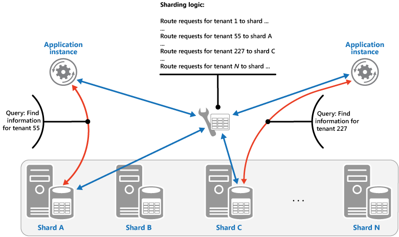
The mapping between the shard key and the physical storage can be based on physical shards where each shard key maps to a physical partition. Alternatively, a more flexible technique for rebalancing shards is virtual partitioning, where shard keys map to the same number of virtual shards, which in turn map to fewer physical partitions. In this approach, an application locates data using a shard key that refers to a virtual shard, and the system transparently maps virtual shards to physical partitions. The mapping between a virtual shard and a physical partition can change without requiring the application code be modified to use a different set of shard keys.
The Range strategy. This strategy groups related items together in the same shard, and orders them by shard key—the shard keys are sequential. It's useful for applications that frequently retrieve sets of items using range queries (queries that return a set of data items for a shard key that falls within a given range). For example, if an application regularly needs to find all orders placed in a given month, this data can be retrieved more quickly if all orders for a month are stored in date and time order in the same shard. If each order was stored in a different shard, they'd have to be fetched individually by performing a large number of point queries (queries that return a single data item). The next figure illustrates storing sequential sets (ranges) of data in shard.
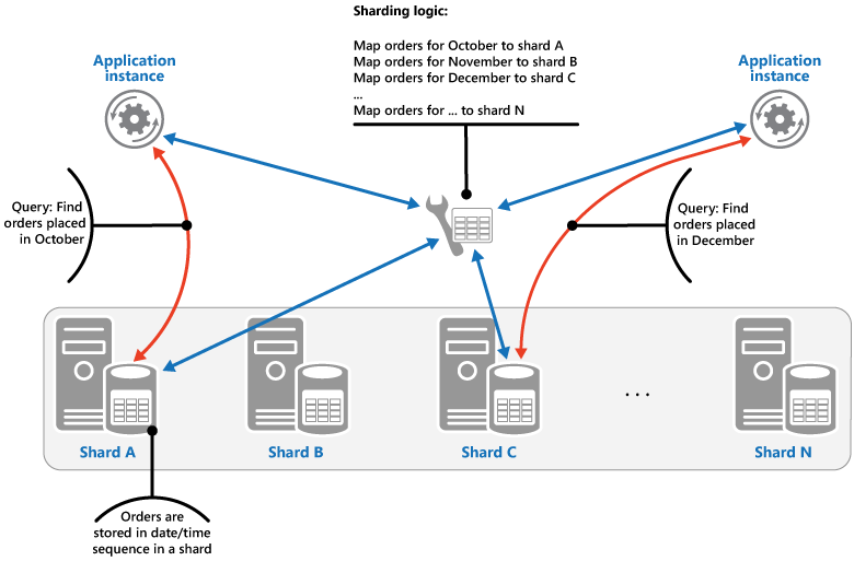
In this example, the shard key is a composite key containing the order month as the most significant element, followed by the order day and the time. The data for orders is naturally sorted when new orders are created and added to a shard. Some data stores support two-part shard keys containing a partition key element that identifies the shard and a row key that uniquely identifies an item in the shard. Data is usually held in row key order in the shard. Items that are subject to range queries and need to be grouped together can use a shard key that has the same value for the partition key but a unique value for the row key.
The Hash strategy. The purpose of this strategy is to reduce the chance of hotspots (shards that receive a disproportionate amount of load). It distributes the data across the shards in a way that achieves a balance between the size of each shard and the average load that each shard will encounter. The sharding logic computes the shard to store an item in based on a hash of one or more attributes of the data. The chosen hashing function should distribute data evenly across the shards, possibly by introducing some random element into the computation. The next figure illustrates sharding tenant data based on a hash of tenant IDs.

To understand the advantage of the Hash strategy over other sharding strategies, consider how a multi-tenant application that enrolls new tenants sequentially might assign the tenants to shards in the data store. When using the Range strategy, the data for tenants 1 to n will all be stored in shard A, the data for tenants n+1 to m will all be stored in shard B, and so on. If the most recently registered tenants are also the most active, most data activity will occur in a small number of shards, which could cause hotspots. In contrast, the Hash strategy allocates tenants to shards based on a hash of their tenant ID. This means that sequential tenants are most likely to be allocated to different shards, which will distribute the load across them. The previous figure shows this for tenants 55 and 56.
The three sharding strategies have the following advantages and considerations:
- Lookup. This offers more control over the way that shards are configured and used. Using virtual shards reduces the impact when rebalancing data because new physical partitions can be added to even out the workload. The mapping between a virtual shard and the physical partitions that implement the shard can be modified without affecting application code that uses a shard key to store and retrieve data. Looking up shard locations can impose an additional overhead.
- Range. This is easy to implement and works well with range queries because they can often fetch multiple data items from a single shard in a single operation. This strategy offers easier data management. For example, if users in the same region are in the same shard, updates can be scheduled in each time zone based on the local load and demand pattern. However, this strategy doesn't provide optimal balancing between shards. Rebalancing shards is difficult and might not resolve the problem of uneven load if the majority of activity is for adjacent shard keys.
- Hash. This strategy offers a better chance of more even data and load distribution. Request routing can be accomplished directly by using the hash function. There's no need to maintain a map. Note that computing the hash might impose an additional overhead. Also, rebalancing shards is difficult.
Most common sharding systems implement one of the approaches described above, but you should also consider the business requirements of your applications and their patterns of data usage. For example, in a multi-tenant application:
- You can shard data based on workload. You could segregate the data for highly volatile tenants in separate shards. The speed of data access for other tenants might be improved as a result.
- You can shard data based on the location of tenants. You can take the data for tenants in a specific geographic region offline for backup and maintenance during off-peak hours in that region, while the data for tenants in other regions remains online and accessible during their business hours.
- High-value tenants could be assigned their own private, high performing, lightly loaded shards, whereas lower-value tenants might be expected to share more densely-packed, busy shards. The data for tenants that need a high degree of data isolation and privacy can be stored on a completely separate server.
- The data for tenants that need a high degree of data isolation and privacy can be stored on a completely separate server.
Scaling and data movement operations
Each of the sharding strategies implies different capabilities and levels of complexity for managing scale in, scale out, data movement, and maintaining state.
The Lookup strategy permits scaling and data movement operations to be carried out at the user level, either online or offline. The technique is to suspend some or all user activity (perhaps during off-peak periods), move the data to the new virtual partition or physical shard, change the mappings, invalidate or refresh any caches that hold this data, and then allow user activity to resume. Often this type of operation can be centrally managed. The Lookup strategy requires state to be highly cacheable and replica friendly.
The Range strategy imposes some limitations on scaling and data movement operations, which must typically be carried out when a part or all of the data store is offline because the data must be split and merged across the shards. Moving the data to rebalance shards might not resolve the problem of uneven load if the majority of activity is for adjacent shard keys or data identifiers that are within the same range. The Range strategy might also require some state to be maintained in order to map ranges to the physical partitions.
The Hash strategy makes scaling and data movement operations more complex because the partition keys are hashes of the shard keys or data identifiers. The new location of each shard must be determined from the hash function, or the function modified to provide the correct mappings.
However, the Hash strategy doesn't require maintenance of state.
Issues and considerations
Consider the following points when deciding how to implement this pattern:
- Sharding is complementary to other forms of partitioning, such as vertical partitioning and functional partitioning. For example, a single shard can contain entities that have been partitioned vertically, and a functional partition can be implemented as multiple shards. For more information about partitioning, see the Data Partitioning Guidance.
- Keep shards balanced so they all handle a similar volume of I/O. As data is inserted and deleted, it's necessary to periodically rebalance the shards to guarantee an even distribution and to reduce the chance of hotspots. Rebalancing can be an expensive operation. To reduce the necessity of rebalancing, plan for growth by ensuring that each shard contains sufficient free space to handle the expected volume of changes. You should also develop strategies and scripts you can use to quickly rebalance shards if this becomes necessary.
- Use stable data for the shard key. If the shard key changes, the corresponding data item might have to move between shards, increasing the amount of work performed by update operations. For this reason, avoid basing the shard key on potentially volatile information. Instead, look for attributes that are invariant or that naturally form a key.
- Ensure that shard keys are unique. For example, avoid using autoincrementing fields as the shard key. Is some systems, autoincremented fields can't be coordinated across shards, possibly resulting in items in different shards having the same shard key.
- Autoincremented values in other fields that are not shard keys can also cause problems. For example, if you use autoincremented fields to generate unique IDs, then two different items located in different shards might be assigned the same ID.
- It might not be possible to design a shard key that matches the requirements of every possible query against the data. Shard the data to support the most frequently performed queries, and if necessary create secondary index tables to support queries that retrieve data using criteria based on attributes that aren't part of the shard key. For more information, see the Index Table pattern.
- Queries that access only a single shard are more efficient than those that retrieve data from multiple shards, so avoid implementing a sharding system that results in applications performing large numbers of queries that join data held in different shards. Remember that a single shard can contain the data for multiple types of entities. Consider denormalizing your data to keep related entities that are commonly queried together (such as the details of customers and the orders that they have placed) in the same shard to reduce the number of separate reads that an application performs.
- If an entity in one shard references an entity stored in another shard, include the shard key for the second entity as part of the schema for the first entity. This can help to improve the performance of queries that reference related data across shards.
- If an application must perform queries that retrieve data from multiple shards, it might be possible to fetch this data by using parallel tasks. Examples include fan-out queries, where data from multiple shards is retrieved in parallel and then aggregated into a single result. However, this approach inevitably adds some complexity to the data access logic of a solution. • For many applications, creating a larger number of small shards can be more efficient than having a small number of large shards because they can offer increased opportunities for load balancing. This can also be useful if you anticipate the need to migrate shards from one physical location to another. Moving a small shard is quicker than moving a large one.
- Make sure the resources available to each shard storage node are sufficient to handle the scalability requirements in terms of data size and throughput. For more information, see the section "Designing Partitions for Scalability" in the Data Partitioning Guidance.
- Consider replicating reference data to all shards. If an operation that retrieves data from a shard also references static or slow-moving data as part of the same query, add this data to the shard. The application can then fetch all of the data for the query easily, without having to make an additional round trip to a separate data store.
- If reference data held in multiple shards changes, the system must synchronize these changes across all shards. The system can experience a degree of inconsistency while this synchronization occurs. If you do this, you should design your applications to be able to handle it.
- It can be difficult to maintain referential integrity and consistency between shards, so you should minimize operations that affect data in multiple shards. If an application must modify data across shards, evaluate whether complete data consistency is actually required. Instead, a common approach in the cloud is to implement eventual consistency. The data in each partition is updated separately, and the application logic must take responsibility for ensuring that the updates all complete successfully, as well as handling the inconsistencies that can arise from querying data while an eventually consistent operation is running. For more information about implementing eventual consistency, see the Data Consistency Primer.
- Configuring and managing a large number of shards can be a challenge. Tasks such as monitoring, backing up, checking for consistency, and logging or auditing must be accomplished on multiple shards and servers, possibly held in multiple locations. These tasks are likely to
- be implemented using scripts or other automation solutions, but that might not completely eliminate the additional administrative requirements.
- Shards can be geolocated so that the data that they contain is close to the instances of an application that use it. This approach can considerably improve performance, but requires additional consideration for tasks that must access multiple shards in different locations.
When to use this pattern
Use this pattern when a data store is likely to need to scale beyond the resources available to a single storage node, or to improve performance by reducing contention in a data store.
The primary focus of sharding is to improve the performance and scalability of a system, but as a by-product it can also improve availability due to how the data is divided into separate partitions. A failure in one partition doesn't necessarily prevent an application from accessing data held in other partitions, and an operator can perform maintenance or recovery of one or more partitions without making the entire data for an application inaccessible. For more information, see the Data Partitioning Guidance.
Example
The following example in C# uses a set of SQL Server databases acting as shards. Each database holds a subset of the data used by an application. The application retrieves data that's distributed across the shards using its own sharding logic (this is an example of a fan-out query). The details of the data that's located in each shard is returned by a method called GetShards. This method returns an enumerable list of ShardInformation objects, where the ShardInformation type contains an identifier for each shard and the SQL Server connection string that an application should use to connect to the shard (the connection strings aren't shown in the code example).
private IEnumerable < ShardInformation > GetShards() {
// This retrieves the connection information from a shard store
// (commonly a root database).
return new [] {
new ShardInformation {
Id = 1,
ConnectionString = ...
},
new ShardInformation {
Id = 2,
ConnectionString = ...
}
};
}
The code below shows how the application uses the list of ShardInformation objects to perform a query that fetches data from each shard in parallel. The details of the query aren't shown, but in this example the data that's retrieved contains a string that could hold information such as the name of a customer if the shards contain the details of customers. The results are aggregated into a ConcurrentBag collection for processing by the application.
// Retrieve the shards as a ShardInformation[] instance.
var shards = GetShards();
var results = new ConcurrentBag < string > ();
// Execute the query against each shard in the shard list.
// This list would typically be retrieved from configuration
// or from a root/master shard store.
Parallel.ForEach(shards, shard => {
// NOTE: Transient fault handling isn't included,
// but should be incorporated when used in a real world application.
using(var con = new SqlConnection(shard.ConnectionString)) {
con.Open();
var cmd = new SqlCommand("SELECT...FROM...", con);
Trace.TraceInformation("Executing command against shard: {
0
}", shard.Id);
var reader = cmd.ExecuteReader();
// Read the results in to a thread-safe data structure.
while (reader.Read()) {
results.Add(reader.GetString(0));
}
}
});
Trace.TraceInformation("Fanout query complete - Record Count: {0}", results.Count);
Related patterns and guidance
The following patterns and guidance may also be relevant when implementing this pattern:
- Data Consistency Primer. It might be necessary to maintain consistency for data distributed across different shards. Summarizes the issues surrounding maintaining consistency over distributed data, and describes the benefits and tradeoffs of different consistency models.
- Data Partitioning Guidance. Sharding a data store can introduce a range of additional issues. Describes these issues in relation to partitioning data stores in the cloud to improve scalability, reduce contention, and optimize performance.
- Index Table pattern. Sometimes it isn't possible to completely support queries just through the design of the shard key. Enables an application to quickly retrieve data from a large data store by specifying a key other than the shard key.
- Materialized View pattern. To maintain the performance of some query operations, it's useful to create materialized views that aggregate and summarize data, especially if this summary data is based on information that's distributed across shards. Describes how to generate and populate these views.
- Shard Lessons on the Adding Simplicity blog.
- Database Sharding on the CodeFutures web site.
- Scalability Strategies Primer: Database Sharding on Max Indelicato's blog.
- Building Scalable Databases: Pros and Cons of Various Database Sharding Schemes on Dare Obasanjo's blog.
Sidecar pattern
Deploy components of an application into a separate process or container to provide isolation and encapsulation. This pattern can also enable applications to be composed of heterogeneous components and technologies.
This pattern is named Sidecar because it resembles a sidecar attached to a motorcycle. In the pattern, the sidecar is attached to a parent application and provides supporting features for the application. The sidecar also shares the same lifecycle as the parent application, being created and retired alongside the parent. The sidecar pattern is sometimes referred to as the sidekick pattern and is a decomposition pattern.
Context and Problem
Applications and services often require related functionality, such as monitoring, logging, configuration, and networking services. These peripheral tasks can be implemented as separate components or services.
If they are tightly integrated into the application, they can run in the same process as the application, making efficient use of shared resources. However, this also means they are not well isolated, and an outage in one of these components can affect other components or the entire application. Also, they usually need to be implemented using the same language as the parent application. As a result, the component and the application have close interdependence on each other.
If the application is decomposed into services, then each service can be built using different languages and technologies. While this gives more flexibility, it means that each component has its own dependencies and requires language-specific libraries to access the underlying platform and any resources shared with the parent application. In addition, deploying these features as separate services can add latency to the application. Managing the code and dependencies for these language-specific interfaces can also add considerable complexity, especially for hosting, deployment, and management.
Solution
Co-locate a cohesive set of tasks with the primary application, but place them inside their own process or container, providing a homogeneous interface for platform services across languages.
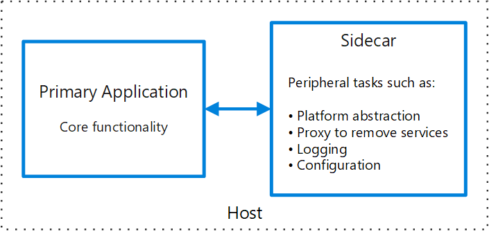
A sidecar service is not necessarily part of the application, but is connected to it. It goes wherever the parent application goes. Sidecars are supporting processes or services that are deployed with the primary application. On a motorcycle, the sidecar is attached to one motorcycle, and each motorcycle can have its own sidecar. In the same way, a sidecar service shares the fate of its parent application. For each instance of the application, an instance of the sidecar is deployed and hosted alongside it.
Advantages of using a sidecar pattern include:
- A sidecar is independent from its primary application in terms of runtime environment and programming language, so you don't need to develop one sidecar per language.
- The sidecar can access the same resources as the primary application. For example, a sidecar can monitor system resources used by both the sidecar and the primary application.
- Because of its proximity to the primary application, there's no significant latency when communicating between them.
- Even for applications that don't provide an extensibility mechanism, you can use a sidecar to extend functionality by attaching it as own process in the same host or sub-container as the primary application.
The sidecar pattern is often used with containers and referred to as a sidecar container or sidekick container.
Issues and Considerations
- Consider the deployment and packaging format you will use to deploy services, processes, or containers. Containers are particularly well suited to the sidecar pattern.
- When designing a sidecar service, carefully decide on the interprocess communication mechanism. Try to use language- or framework-agnostic technologies unless performance requirements make that impractical.
- Before putting functionality into a sidecar, consider whether it would work better as a separate service or a more traditional daemon.
- Also consider whether the functionality could be implemented as a library or using a traditional extension mechanism. Language-specific libraries may have a deeper level of integration and less network overhead.
When to Use this Pattern
Use this pattern when:
- Your primary application uses a heterogenous set of languages and frameworks. A component located in a sidecar service can be consumed by applications written in different languages using different frameworks.
- A component is owned by a remote team or a different organization.
- A component or feature must be co-located on the same host as the application. You need a service that shares the overall lifecycle of your main application, but can be independently updated.
- You need fine-grained control over resource limits for a particular resource or component. For example, you may want to restrict the amount of memory a specific component uses. You can deploy the component as a sidecar and manage memory usage independently of the main application.
This pattern may not be suitable:
- When interprocess communication needs to be optimized. Communication between a parent application and sidecar services includes some overhead, notably latency in the calls. This may not be an acceptable trade-off for chatty interfaces.
- For small applications where the resource cost of deploying a sidecar service for each instance is not worth the advantage of isolation.
- When the service needs to scale differently than or independently from the main applications. If so, it may be better to deploy the feature as a separate service.
Example
The sidecar pattern is applicable to many scenarios. Some common examples:
- Infrastructure API. The infrastructure development team creates a service that's deployed alongside each application, instead of a language-specific client library to access the infrastructure. The service is loaded as a sidecar and provides a common layer for infrastructure services, including logging, environment data, configuration store, discovery, health checks, and watchdog services. The sidecar also monitors the parent application's host environment and process (or container) and logs the information to a centralized service.
- Manage NGINX/HAProxy. Deploy NGINX with a sidecar service that monitors environment state, then updates the NGINX configuration file and recycles the process when a change in state is needed.
- Ambassador sidecar. Deploy an ambassador service as a sidecar. The application calls through the ambassador, which handles request logging, routing, circuit breaking, and other connectivity related features.
- Offload proxy. Place an NGINX proxy in front of a node.js service instance, to handle serving static file content for the service
Related guidance
Static Content Hosting pattern
Deploy static content to a cloud-based storage service that can deliver them directly to the client. This can reduce the need for potentially expensive compute instances.
Context and problem
Web applications typically include some elements of static content. This static content might include HTML pages and other resources such as images and documents that are available to the client, either as part of an HTML page (such as inline images, style sheets, and client-side JavaScript files) or as separate downloads (such as PDF documents).
Although web servers are well tuned to optimize requests through efficient dynamic page code execution and output caching, they still have to handle requests to download static content. This consumes processing cycles that could often be put to better use.
Solution
In most cloud hosting environments it's possible to minimize the need for compute instances (for example, use a smaller instance or fewer instances), by locating some of an application's resources and static pages in a storage service. The cost for cloud-hosted storage is typically much less than for compute instances.
When hosting some parts of an application in a storage service, the main considerations are related to deployment of the application and to securing resources that aren't intended to be available to anonymous users.
Issues and considerations
Consider the following points when deciding how to implement this pattern:
- The hosted storage service must expose an HTTP endpoint that users can access to download the static resources. Some storage services also support HTTPS, so it's possible to host resources in storage services that require SSL.
- For maximum performance and availability, consider using a content delivery network (CDN) to cache the contents of the storage container in multiple datacenters around the world. However, you'll likely have to pay for using the CDN.
- Storage accounts are often geo-replicated by default to provide resiliency against events that might affect a datacenter. This means that the IP address might change, but the URL will remain the same.
- When some content is located in a storage account and other content is in a hosted compute instance it becomes more challenging to deploy an application and to update it. You might have to perform separate deployments, and version the application and content to manage it more easily—especially when the static content includes script files or UI components. However, if only static resources have to be updated, they can simply be uploaded to the storage account without needing to redeploy the application package.
- Storage services might not support the use of custom domain names. In this case it's necessary to specify the full URL of the resources in links because they'll be in a different domain from the dynamically-generated content containing the links.
- The storage containers must be configured for public read access, but it's vital to ensure that they aren't configured for public write access to prevent users being able to upload content. Consider using a valet key or token to control access to resources that shouldn't be available anonymously—see the Valet Key pattern for more information.
When to use this pattern
This pattern is useful for:
- Minimizing the hosting cost for websites and applications that contain some static resources.
- Minimizing the hosting cost for websites that consist of only static content and resources. Depending on the capabilities of the hosting provider's storage system, it might be possible to entirely host a fully static website in a storage account.
- Exposing static resources and content for applications running in other hosting environments or on-premises servers.
- Locating content in more than one geographical area using a content delivery network that caches the contents of the storage account in multiple datacenters around the world.
- Monitoring costs and bandwidth usage. Using a separate storage account for some or all of the static content allows the costs to be more easily separated from hosting and runtime costs.
This pattern may not be useful in the following situations:
- The application needs to perform some processing on the static content before delivering it to the client. For example, it might be necessary to add a timestamp to a document.
- The volume of static content is very small. The overhead of retrieving this content from separate storage can outweigh the cost benefit of separating it out from the compute resource.
Example
Static content located in Azure Blob storage can be accessed directly by a web browser. Azure provides an HTTP-based interface over storage that can be publicly exposed to clients. For example, content in an Azure Blob storage container is exposed using a URL with the following form:
http://[ storage-account-name ].blob.core.windows.net/[ container-name ]/[ file-name ]
When uploading the content it's necessary to create one or more blob containers to hold the files and documents. Note that the default permission for a new container is Private, and you must change this to Public to allow clients to access the contents. If it's necessary to protect the content from anonymous access, you can implement the Valet Key pattern so users must present a valid token to download the resources.
Blob Service Concepts has information about blob storage, and the ways that you can access and use it.
The links in each page will specify the URL of the resource and the client will access it directly from the storage service. The figure illustrates delivering static parts of an application directly from a storage service.

The links in the pages delivered to the client must specify the full URL of the blob container and resource. For example, a page that contains a link to an image in a public container might contain the following HTML.
<img src="http://mystorageaccount.blob.core.windows.net/myresources/image1.png" alt="My image" />
If the resources are protected by using a valet key, such as an Azure shared access signature, this signature must be included in the URLs in the links.
A solution named StaticContentHosting that demonstrates using external storage for static resources is available from GitHub. The StaticContentHosting.Cloud project contains configuration files that specify the storage account and container that holds the static content.
<Setting name="StaticContent.StorageConnectionString" value="UseDevelopmentStorage=true" /> <Setting name="StaticContent.Container" value="static-content" />
The Settings class in the file Settings.cs of the StaticContentHosting.Web project contains methods to extract these values and build a string value containing the cloud storage account container URL.
public class Settings {
public static string StaticContentStorageConnectionString {
get {
return RoleEnvironment.GetConfigurationSettingValue("StaticContent.StorageConnectionString");
}
}
public static string StaticContentContainer {
get {
return RoleEnvironment.GetConfigurationSettingValue("StaticContent.Container");
}
}
public static string StaticContentBaseUrl {
get {
var account = CloudStorageAccount.Parse(StaticContentStorageConnectionString);
return string.Format("{0}/{1}", account.BlobEndpoint.ToString().TrimEnd('/'), StaticContentContainer.TrimStart('/'));
}
}
}
The StaticContentUrlHtmlHelper class in the file StaticContentUrlHtmlHelper.cs exposes a method named StaticContentUrl that generates a URL containing the path to the cloud storage account if the URL passed to it starts with the ASP.NET root path character (~).
public static class StaticContentUrlHtmlHelper {
public static string StaticContentUrl(this HtmlHelper helper, string contentPath) {
if (contentPath.StartsWith("~")) {
contentPath = contentPath.Substring(1);
}
contentPath = string.Format("{0}/{1}", Settings.StaticContentBaseUrl.TrimEnd('/'), contentPath.TrimStart('/'));
var url = new UrlHelper(helper.ViewContext.RequestContext);
return url.Content(contentPath);
}
}
The file Index.cshtml in the Views\Home folder contains an image element that uses the StaticContentUrl method to create the URL for its src attribute.
<img src="@Html.StaticContentUrl("~/media/orderedList1.png")" alt="Test Image" />
Related patterns and guidance
- A sample that demonstrates this pattern is available on GitHub.
- Valet Key pattern. If the target resources aren't supposed to be available to anonymous users it's necessary to implement security over the store that holds the static content. Describes how to use a token or key that provides clients with restricted direct access to a specific resource or service such as a cloud-hosted storage service.
- An efficient way of deploying a static web site on Azure on the Infosys blog.
- Blob Service Concepts
Strangler pattern
Incrementally migrate a legacy system by gradually replacing specific pieces of functionality with new applications and services. As features from the legacy system are replaced, the new system eventually replaces all of the old system's features, strangling the old system and allowing you to decommission it.
Context and problem
As systems age, the development tools, hosting technology, and even system architectures they were built on can become increasingly obsolete. As new features and functionality are added, the complexity of these applications can increase dramatically, making them harder to maintain or add new features to.
Completely replacing a complex system can be a huge undertaking. Often, you will need a gradual migration to a new system, while keeping the old system to handle features that haven't been migrated yet. However, running two separate versions of an application means that clients have to know where particular features are located. Every time a feature or service is migrated, clients need to be updated to point to the new location.
Solution
Incrementally replace specific pieces of functionality with new applications and services. Create a façade that intercepts requests going to the backend legacy system. The façade routes these requests either to the legacy application or the new services. Existing features can be migrated to the new system gradually, and consumers can continue using the same interface, unaware that any migration has taken place.

This pattern helps to minimize risk from the migration, and spread the development effort over time. With the façade safely routing users to the correct application, you can add functionality to the new system at whatever pace you like, while ensuring the legacy application continues to function. Over time, as features are migrated to the new system, the legacy system is eventually "strangled" and is no longer necessary. Once this process is complete, the legacy system can safely be retired.
Issues and considerations
- Consider how to handle services and data stores that are potentially used by both new and legacy systems. Make sure both can access these resources side-by-side.
- Structure new applications and services in a way that they can easily be intercepted and replaced in future strangler migrations.
- At some point, when the migration is complete, the strangler façade will either go away or evolve into an adaptor for legacy clients.
- Make sure the façade keeps up with the migration.
- Make sure the façade doesn't become a single point of failure or a performance bottleneck.
When to use this pattern
Use this pattern when gradually migrating a back-end application to a new architecture.
This pattern may not be suitable:
- When requests to the back-end system cannot be intercepted.
- For smaller systems where the complexity of wholesale replacement is low.
Related guidance
Throttling pattern
Control the consumption of resources used by an instance of an application, an individual tenant, or an entire service. This can allow the system to continue to function and meet service level agreements, even when an increase in demand places an extreme load on resources.
Context and problem
The load on a cloud application typically varies over time based on the number of active users or the types of activities they are performing. For example, more users are likely to be active during business hours, or the system might be required to perform computationally expensive analytics at the end of each month. There might also be sudden and unanticipated bursts in activity. If the processing requirements of the system exceed the capacity of the resources that are available, it'll suffer from poor performance and can even fail. If the system has to meet an agreed level of service, such failure could be unacceptable.
There're many strategies available for handling varying load in the cloud, depending on the business goals for the application. One strategy is to use autoscaling to match the provisioned resources to the user needs at any given time. This has the potential to consistently meet user demand, while optimizing running costs. However, while autoscaling can trigger the provisioning of additional resources, this provisioning isn't immediate. If demand grows quickly, there can be a window of time where there's a resource deficit.
Solution
An alternative strategy to autoscaling is to allow applications to use resources only up to a limit, and then throttle them when this limit is reached. The system should monitor how it's using resources so that, when usage exceeds the threshold, it can throttle requests from one or more users. This will enable the system to continue functioning and meet any service level agreements (SLAs) that are in place. For more information on monitoring resource usage, see the Instrumentation and Telemetry Guidance.
The system could implement several throttling strategies, including:
- Rejecting requests from an individual user who's already accessed system APIs more than n times per second over a given period of time. This requires the system to meter the use of resources for each tenant or user running an application. For more information, see the Service Metering Guidance.
- Disabling or degrading the functionality of selected nonessential services so that essential services can run unimpeded with sufficient resources. For example, if the application is streaming video output, it could switch to a lower resolution.
- Using load leveling to smooth the volume of activity (this approach is covered in more detail by the Queue-based Load Leveling pattern). In a multi-tenant environment, this approach will reduce the performance for every tenant. If the system must support a mix of tenants with different SLAs, the work for high-value tenants might be performed immediately. Requests for other tenants can be held back, and handled when the backlog has eased. The Priority Queue pattern could be used to help implement this approach.
- Deferring operations being performed on behalf of lower priority applications or tenants. These operations can be suspended or limited, with an exception generated to inform the tenant that the system is busy and that the operation should be retried later.
The figure shows an area graph for resource use (a combination of memory, CPU, bandwidth, and other factors) against time for applications that are making use of three features. A feature is an area of functionality, such as a component that performs a specific set of tasks, a piece of code that performs a complex calculation, or an element that provides a service such as an in-memory cache. These features are labeled A, B, and C.

The area immediately below the line for a feature indicates the resources that are used by applications when they invoke this feature. For example, the area below the line for Feature A shows the resources used by applications that are making use of Feature A, and the area between the lines for Feature A and Feature B indicates the resources used by applications invoking Feature B. Aggregating the areas for each feature shows the total resource use of the system.
The previous figure illustrates the effects of deferring operations. Just prior to time T1, the total resources allocated to all applications using these features reach a threshold (the limit of resource use). At this point, the applications are in danger of exhausting the resources available. In this system, Feature B is less critical than Feature A or Feature C, so it's temporarily disabled and the resources that it was using are released. Between times T1 and T2, the applications using Feature A and Feature C continue running as normal. Eventually, the resource use of these two features diminishes to the point when, at time T2, there is sufficient capacity to enable Feature B again.
The autoscaling and throttling approaches can also be combined to help keep the applications responsive and within SLAs. If the demand is expected to remain high, throttling provides a temporary solution while the system scales out. At this point, the full functionality of the system can be restored.
The next figure shows an area graph of the overall resource use by all applications running in a system against time, and illustrates how throttling can be combined with autoscaling.

At time T1, the threshold specifying the soft limit of resource use is reached. At this point, the system can start to scale out. However, if the new resources don't become available quickly enough, then the existing resources might be exhausted and the system could fail. To prevent this from occurring, the system is temporarily throttled, as described earlier. When autoscaling has completed and the additional resources are available, throttling can be relaxed.
Issues and considerations
You should consider the following points when deciding how to implement this pattern:
- Throttling an application, and the strategy to use, is an architectural decision that impacts the entire design of a system. Throttling should be considered early in the application design process because it isn't easy to add once a system has been implemented.
- Throttling must be performed quickly. The system must be capable of detecting an increase in activity and react accordingly. The system must also be able to revert to its original state quickly after the load has eased. This requires that the appropriate performance data is continually captured and monitored.
- If a service needs to temporarily deny a user request, it should return a specific error code so the client application understands that the reason for the refusal to perform an operation is due to throttling. The client application can wait for a period before retrying the request.
- Throttling can be used as a temporary measure while a system autoscales. In some cases it's better to simply throttle, rather than to scale, if a burst in activity is sudden and isn't expected to be long lived because scaling can add considerably to running costs.
- If throttling is being used as a temporary measure while a system autoscales, and if resource demands grow very quickly, the system might not be able to continue functioning—even when operating in a throttled mode. If this isn't acceptable, consider maintaining larger capacity reserves and configuring more aggressive autoscaling.
When to use this pattern
Use this pattern:
- To ensure that a system continues to meet service level agreements.
- To prevent a single tenant from monopolizing the resources provided by an application.
- To handle bursts in activity.
- To help cost-optimize a system by limiting the maximum resource levels needed to keep it functioning.
Example
The final figure illustrates how throttling can be implemented in a multi-tenant system. Users from each of the tenant organizations access a cloud-hosted application where they fill out and submit surveys. The application contains instrumentation that monitors the rate at which these users are submitting requests to the application.
In order to prevent the users from one tenant affecting the responsiveness and availability of the application for all other users, a limit is applied to the number of requests per second the users from any one tenant can submit. The application blocks requests that exceed this limit.

Related patterns and guidance
The following patterns and guidance may also be relevant when implementing this pattern:
- Instrumentation and Telemetry Guidance. Throttling depends on gathering information about how heavily a service is being used. Describes how to generate and capture custom monitoring information.
- Service Metering Guidance. Describes how to meter the use of services in order to gain an understanding of how they are used. This information can be useful in determining how to throttle a service.
- Autoscaling Guidance. Throttling can be used as an interim measure while a system autoscales, or to remove the need for a system to autoscale. Contains information on autoscaling strategies.
- Queue-based Load Leveling pattern. Queue-based load leveling is a commonly used mechanism for implementing throttling. A queue can act as a buffer that helps to even out the rate at which requests sent by an application are delivered to a service.
- Priority Queue pattern. A system can use priority queuing as part of its throttling strategy to maintain performance for critical or higher value applications, while reducing the performance of less important applications.
Valet Key pattern
Use a token that provides clients with restricted direct access to a specific resource in order to offload data transfer from the application. This is particularly useful in applications that use cloud-hosted storage systems or queues, and can minimize cost and maximize scalability and performance.
Context and problem
Client programs and web browsers often need to read and write files or data streams to and from an application's storage. Typically, the application will handle the movement of the data — either by fetching it from storage and streaming it to the client, or by reading the uploaded stream from the client and storing it in the data store. However, this approach absorbs valuable resources such as compute, memory, and bandwidth.
Data stores have the ability to handle the upload and download of data directly, without requiring that the application perform any processing to move this data. But this typically requires the client to have access to the security credentials for the store. This can be a useful technique to minimize data transfer costs and the requirement to scale out the application, and to maximize performance. It means, though, that the application is no longer able to manage the security of the data. After the client has a connection to the data store for direct access, the application can't act as the gatekeeper. It's no longer in control of the process and can't prevent subsequent uploads or downloads from the data store.
This isn't a realistic approach in distributed systems that need to serve untrusted clients. Instead, applications must be able to securely control access to data in a granular way, but still reduce the load on the server by setting up this connection and then allowing the client to communicate directly with the data store to perform the required read or write operations.
Solution
You need to resolve the problem of controlling access to a data store where the store can't manage authentication and authorization of clients. One typical solution is to restrict access to the data store's public connection and provide the client with a key or token that the data store can validate.
This key or token is usually referred to as a valet key. It provides time-limited access to specific resources and allows only predefined operations such as reading and writing to storage or queues, or uploading and downloading in a web browser. Applications can create and issue valet keys to client devices and web browsers quickly and easily, allowing clients to perform the required operations without requiring the application to directly handle the data transfer. This removes the processing overhead, and the impact on performance and scalability, from the application and the server.
The client uses this token to access a specific resource in the data store for only a specific period, and with specific restrictions on access permissions, as shown in the figure. After the specified period, the key becomes invalid and won't allow access to the resource.

It's also possible to configure a key that has other dependencies, such as the scope of the data. For example, depending on the data store capabilities, the key can specify a complete table in a data store, or only specific rows in a table. In cloud storage systems the key can specify a container or just a specific item within a container.
The key can also be invalidated by the application. This is a useful approach if the client notifies the server that the data transfer operation is complete. The server can then invalidate that key to prevent further.
Using this pattern can simplify managing access to resources because there's no requirement to create and authenticate a user, grant permissions, and then remove the user again. It also makes it easy to limit the location, the permission, and the validity period—all by simply generating a key at runtime. The important factors are to limit the validity period, and especially the location of the resource, as tightly as possible so that the recipient can only use it for the intended purpose.
Issues and considerations
Consider the following points when deciding how to implement this pattern:
Manage the validity status and period of the key. If leaked or compromised, the key effectively unlocks the target item and makes it available for malicious use during the validity period. A key can usually be revoked or disabled, depending on how it was issued. Server-side policies can be changed or, the server key it was signed with can be invalidated. Specify a short validity period to minimize the risk of allowing unauthorized operations to take place against the data store. However, if the validity period is too short, the client might not be able to complete the operation before the key expires. Allow authorized users to renew the key before the validity period expires if multiple accesses to the protected resource are required.
Control the level of access the key will provide. Typically, the key should allow the user to only perform the actions necessary to complete the operation, such as read-only access if the client shouldn't be able to upload data to the data store. For file uploads, it's common to specify a key that provides write-only permission, as well as the location and the validity period. It's critical to accurately specify the resource or the set of resources to which the key applies.
Consider how to control users' behavior. Implementing this pattern means some loss of control over the resources users are granted access to. The level of control that can be exerted is limited by the capabilities of the policies and permissions available for the service or the target data store. For example, it's usually not possible to create a key that limits the size of the data to be written to storage, or the number of times the key can be used to access a file. This can result in huge unexpected costs for data transfer, even when used by the intended client, and might be caused by an error in the code that causes repeated upload or download. To limit the number of times a file can be uploaded, where possible, force the client to notify the application when one operation has completed. For example, some data stores raise events the application code can use to monitor operations and control user behavior. However, it's hard to enforce quotas for individual users in a multi-tenant scenario where the same key is used by all the users from one tenant.
Validate, and optionally sanitize, all uploaded data. A malicious user that gains access to the key could upload data designed to compromise the system. Alternatively, authorized users might upload data that's invalid and, when processed, could result in an error or system failure. To protect against this, ensure that all uploaded data is validated and checked for malicious content before use.
Audit all operations. Many key-based mechanisms can log operations such as uploads, downloads, and failures. These logs can usually be incorporated into an audit process, and also used for billing if the user is charged based on file size or data volume. Use the logs to detect authentication failures that might be caused by issues with the key provider, or accidental removal of a stored access policy.
Deliver the key securely. It can be embedded in a URL that the user activates in a web page, or it can be used in a server redirection operation so that the download occurs automatically. Always use HTTPS to deliver the key over a secure channel.
Protect sensitive data in transit. Sensitive data delivered through the application will usually take place using SSL or TLS, and this should be enforced for clients accessing the data store directly.
Other issues to be aware of when implementing this pattern are:
- If the client doesn't, or can't, notify the server of completion of the operation, and the only limit is the expiration period of the key, the application won't be able to perform auditing operations such as counting the number of uploads or downloads, or preventing multiple uploads or downloads.
- The flexibility of key policies that can be generated might be limited. For example, some mechanisms only allow the use of a timed expiration period. Others aren't able to specify a sufficient granularity of read/write permissions.
- If the start time for the key or token validity period is specified, ensure that it's a little earlier than the current server time to allow for client clocks that might be slightly out of synchronization. The default, if not specified, is usually the current server time.
- The URL containing the key will be recorded in server log files. While the key will typically have expired before the log files are used for analysis, ensure that you limit access to them. If log data is transmitted to a monitoring system or stored in another location, consider implementing a delay to prevent leakage of keys until after their validity period has expired.
- If the client code runs in a web browser, the browser might need to support cross-origin resource sharing (CORS) to enable code that executes within the web browser to access data in a different domain from the one that served the page. Some older browsers and some data stores don't support CORS, and code that runs in these browsers might be able to use a valet key to provide access to data in a different domain, such as a cloud storage account.
When to use this pattern
This pattern is useful for the following situations:
- To minimize resource loading and maximize performance and scalability. Using a valet key doesn't require the resource to be locked, no remote server call is required, there's no limit on the number of valet keys that can be issued, and it avoids a single point of failure resulting from performing the data transfer through the application code. Creating a valet key is typically a simple cryptographic operation of signing a string with a key.
- To minimize operational cost. Enabling direct access to stores and queues is resource and cost efficient, can result in fewer network round trips, and might allow for a reduction in the number of compute resources required.
- When clients regularly upload or download data, particularly where there's a large volume or when each operation involves large files.
- When the application has limited compute resources available, either due to hosting limitations or cost considerations. In this scenario, the pattern is even more helpful if there are many concurrent data uploads or downloads because it relieves the application from handling the data transfer.
- When data is stored in a remote data store or a different datacenter. If the application was required to act as a gatekeeper, there might be a charge for the additional bandwidth of transferring the data between datacenters, or across public or private networks between the client and the application, and then between the application and the data store.
This pattern might not be useful in the following situations:
- If the application must perform some task on the data before it's stored or before it's sent to the client. For example, if the application needs to perform validation, log access success, or execute a transformation on the data. However, some data stores and clients are able to negotiate and carry out simple transformations such as compression and decompression (for example, a web browser can usually handle GZip formats).
- If the design of an existing application makes it difficult to incorporate the pattern. Using this pattern typically requires a different architectural approach for delivering and receiving data.
Example
Azure supports shared access signatures on Azure Storage for granular access control to data in blobs, tables, and queues, and for Service Bus queues and topics. A shared access signature token can be configured to provide specific access rights such as read, write, update, and delete to a specific table; a key range within a table; a queue; a blob; or a blob container. The validity can be a specified time period or with no time limit.
Azure shared access signatures also support server-stored access policies that can be associated with a specific resource such as a table or blob. This feature provides additional control and flexibility compared to application-generated shared access signature tokens, and should be used whenever possible. Settings defined in a server-stored policy can be changed and are reflected in the token without requiring a new token to be issued, but settings defined in the token can't be changed without issuing a new token. This approach also makes it possible to revoke a valid shared access signature token before it's expired.
For more information see Introducing Table SAS (Shared Access Signature), Queue SAS and update to Blob SAS and Using Shared Access Signatures on MSDN.
The following code shows how to create a shared access signature token that's valid for five minutes. The "GetSharedAccessReferenceForUpload" method returns a shared access signatures token that can be used to upload a file to Azure Blob Storage.
public class ValuesController: ApiController {
private readonly CloudStorageAccount account;
private readonly string blobContainer;
...
/// <summary>
/// Return a limited access key that allows the caller to upload a file
/// to this specific destination for a defined period of time.
/// </summary>
private StorageEntitySas GetSharedAccessReferenceForUpload(string blobName) {
var blobClient = this.account.CreateCloudBlobClient();
var container = blobClient.GetContainerReference(this.blobContainer);
var blob = container.GetBlockBlobReference(blobName);
var policy = new SharedAccessBlobPolicy {
Permissions = SharedAccessBlobPermissions.Write,
// Specify a start time five minutes earlier to allow for client clock skew.
SharedAccessStartTime = DateTime.UtcNow.AddMinutes(-5),
// Specify a validity period of five minutes starting from now.
SharedAccessExpiryTime = DateTime.UtcNow.AddMinutes(5)
};
// Create the signature.
var sas = blob.GetSharedAccessSignature(policy);
return new StorageEntitySas {
BlobUri = blob.Uri,
Credentials = sas,
Name = blobName
};
}
public struct StorageEntitySas {
public string Credentials;
public Uri BlobUri;
public string Name;
}
}
The complete sample is available in the ValetKey solution available for download from GitHub. The ValetKey.Web project in this solution contains a web application that includes the ValuesController class shown above. A sample client application that uses this web application to retrieve a shared access signatures key and upload a file to blob storage is available in the ValetKey.Client project.
Next steps
The following patterns and guidance may also be relevant when implementing this pattern:
- A sample that demonstrates this pattern is available on GitHub.
- Gatekeeper Pattern. This pattern can be used in conjunction with the Valet Key pattern to protect applications and services by using a dedicated host instance that acts as a broker between clients and the application or service. The gatekeeper validates and sanitizes requests, and passes requests and data between the client and the application. Can provide an additional layer of security, and reduce the attack surface of the system.
- Static Content Hosting Pattern. Describes how to deploy static resources to a cloud-based storage service that can deliver these resources directly to the client to reduce the requirement for expensive compute instances. Where the resources aren't intended to be publicly available, the Valet Key pattern can be used to secure them.
- Introducing Table SAS (Shared Access Signature), Queue SAS and update to Blob SAS
- Using Shared Access Signatures
- Shared Access Signature Authentication with Service Bus